Hi everyone,
This is Part 2 of our series on the TONUS Wearable Devices (TWD), a wearable optical sensor platform we are building at ETH Zurich (tonus.dev) for research on cuffless blood-pressure monitoring. Read Part 1 here
In Part 1, our first custom board (TWD1) used discrete LEDs, photodiodes and an analogue front end, and never produced a reliable signal. Our conclusion was to stop designing the most sensitive part of the optical chain ourselves. This post shows what happened when we did that (TWD2), and what happened when we then tried to put everything on one board (TWD3).
TWD2: using an integrated optical sensor
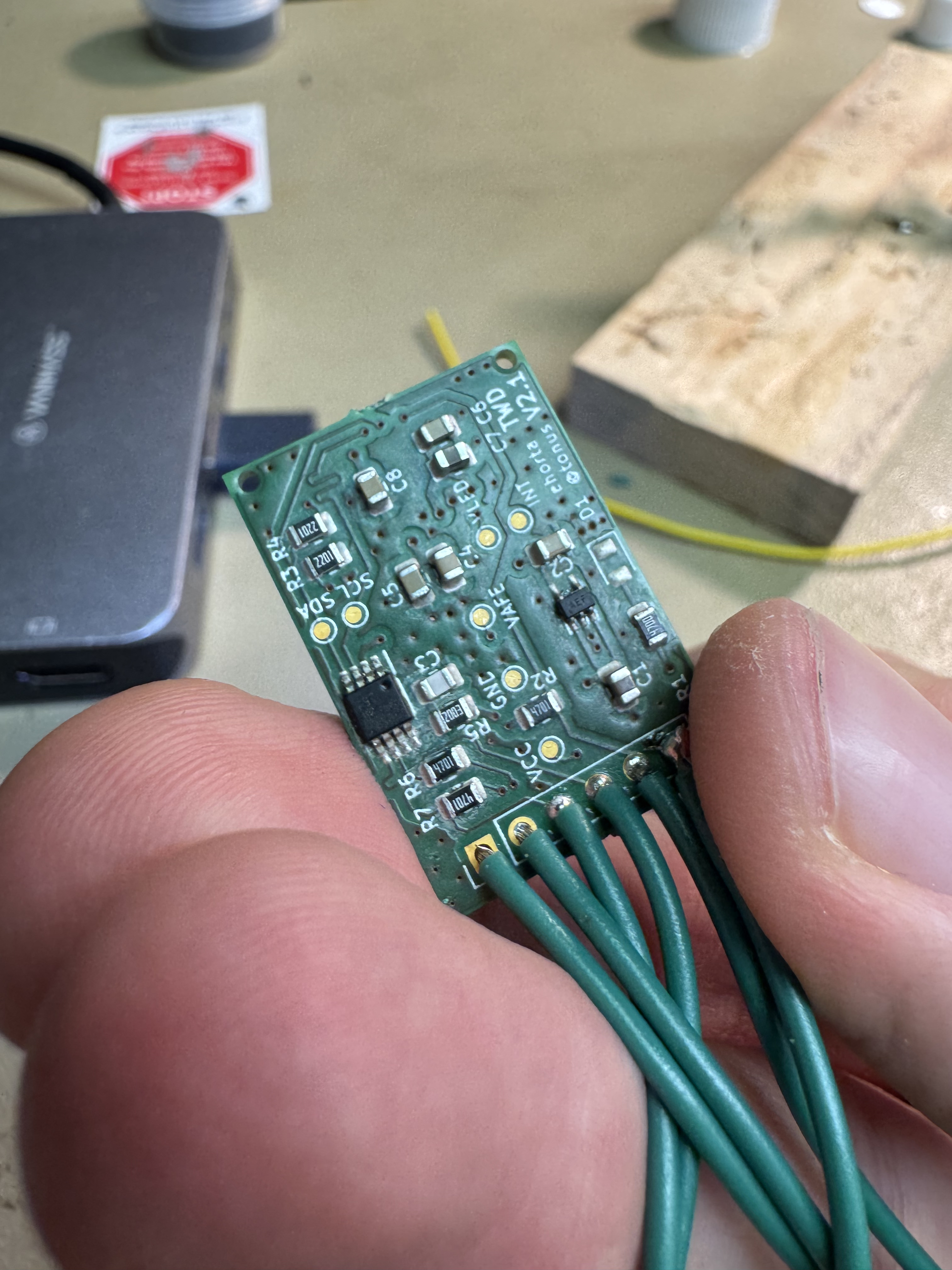
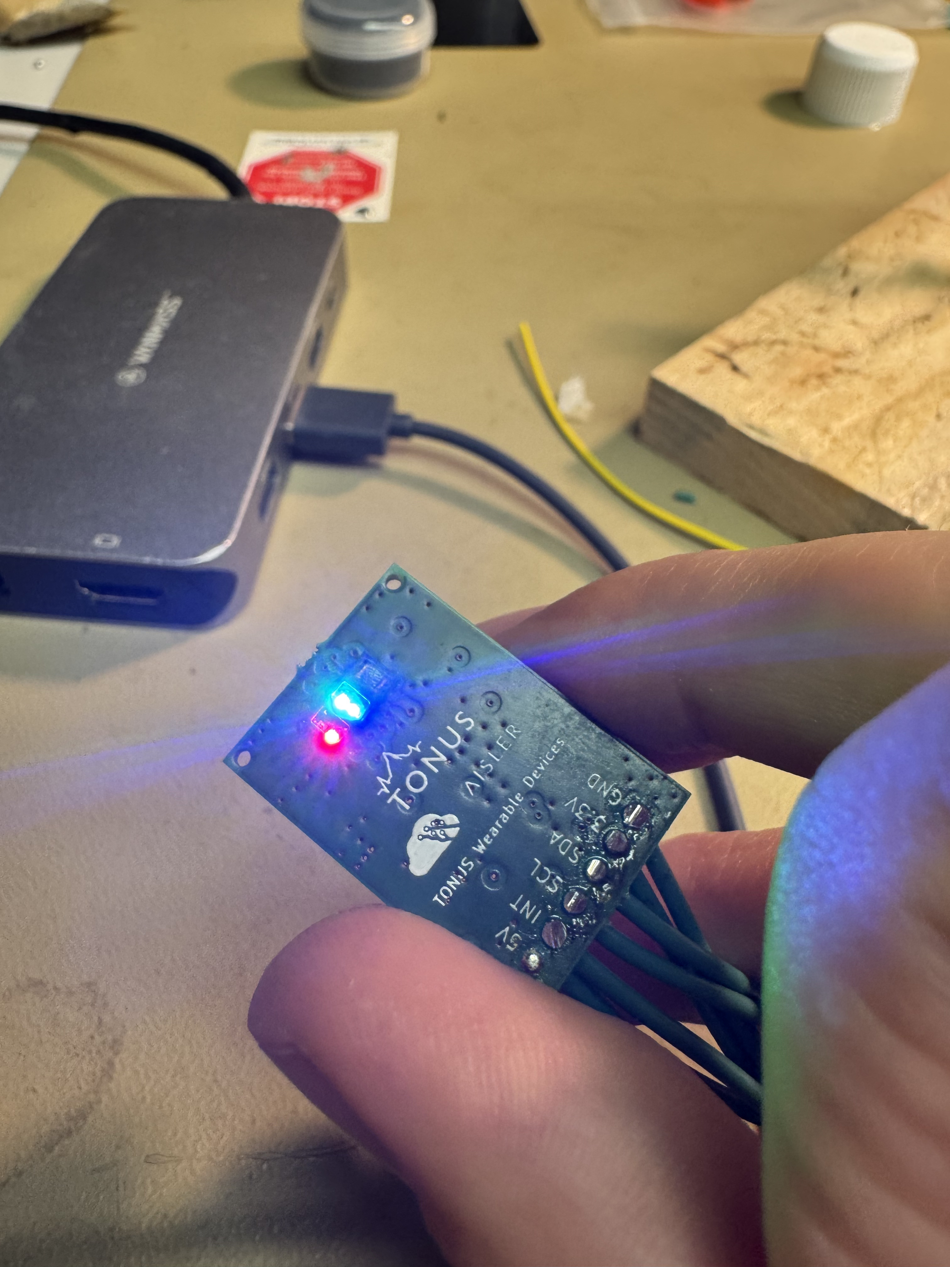
For TWD2 we built the board around the Maxim/Analog Devices MAX86916. It is a small optical module made for wearables that contains in one package:
- four LEDs (infrared, red, green and blue),
- photodetectors,
- the low-noise analogue front end and ADC,
- ambient-light cancellation.
It is configured and read over I2C. It needs a 1.8 V logic supply and a separate LED supply, which we kept as two clearly separated rails on the board.
Our greatest win: the first clean four-channel signal
TWD2 was the first board that gave us a reliable PPG signal on all four wavelengths. Compared with TWD1, three things changed for us:
- Much less analogue risk. LED and photodetector placement and the amplifier are fixed by the sensor manufacturer. We still had to get contact and mechanics right, but we were no longer debugging our own front end at the same time.
- Repeatable experiments. LED current, LED range, pulse width, sample averaging, ADC range and sample rate are all register settings. If a channel saturates at one body position or is too weak at another, we change the configuration and record it together with the data, instead of changing hardware.
- More research questions with the same board. Four wavelengths on one sensor let us compare channels against each other under the same conditions.
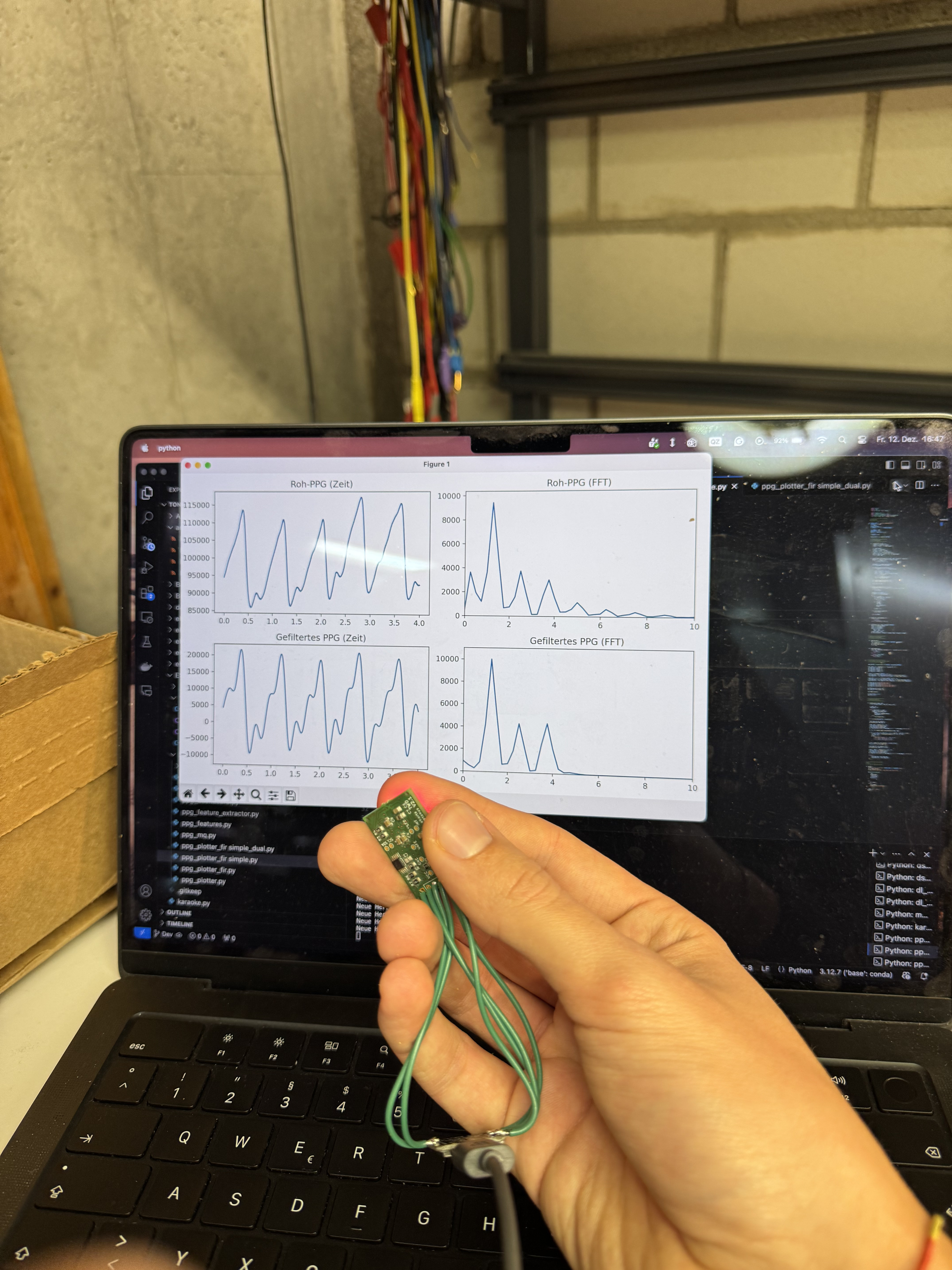
With a sensor that worked, we started placing several boards on the body at once.
TWD3: one board for everything
TWD2 was a sensor board only. The next step looked logical: TWD3 combined everything into one compact module:
- the MAX86916 optical sensor,
- a wireless microcontroller,
- an IMU and magnetometer,
- a skin-temperature sensor and a barometric pressure sensor,
- power supply for all of it.
The extra sensors record motion and environmental context together with the optical signal, which we need to interpret the PPG data.
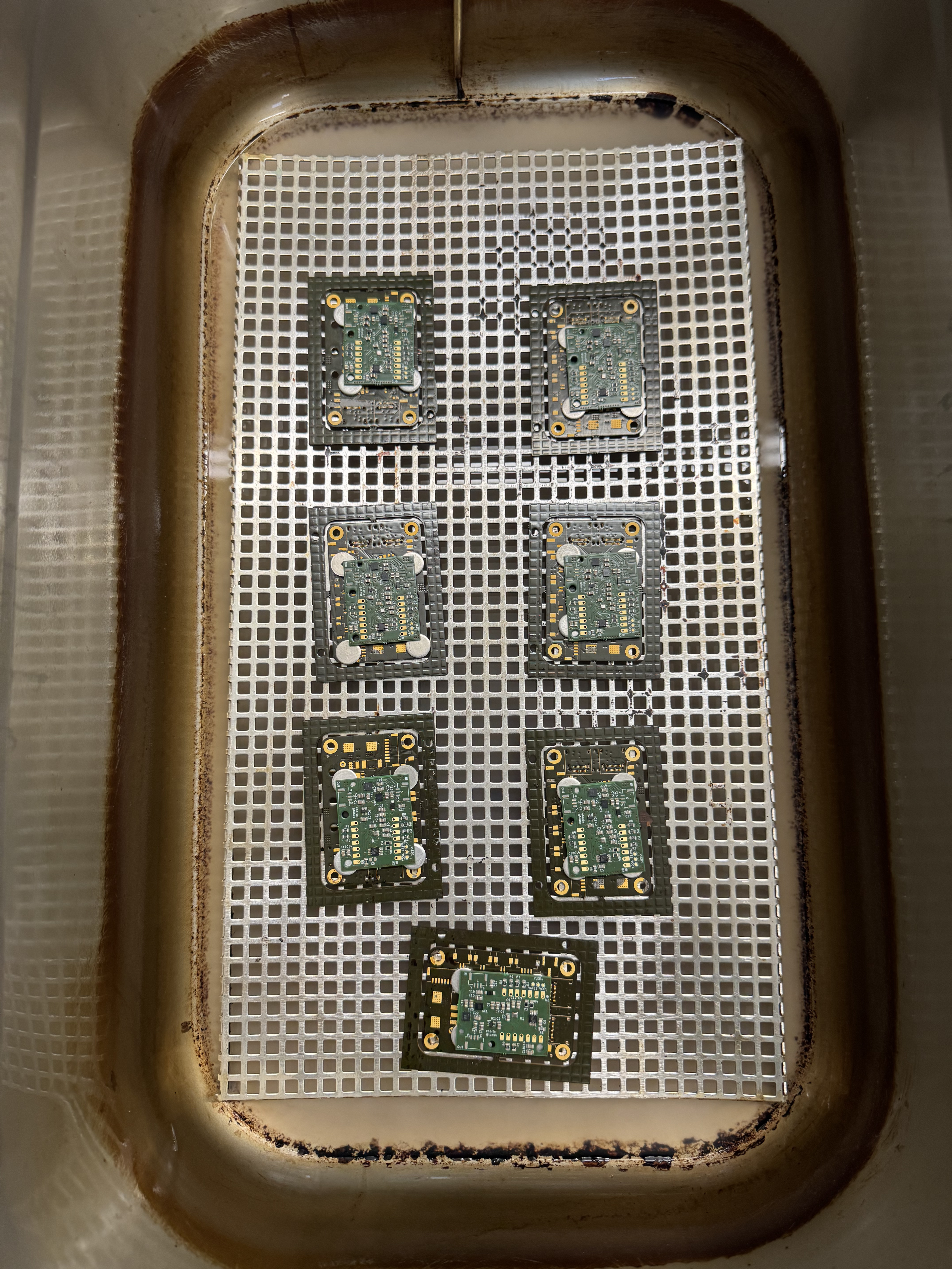
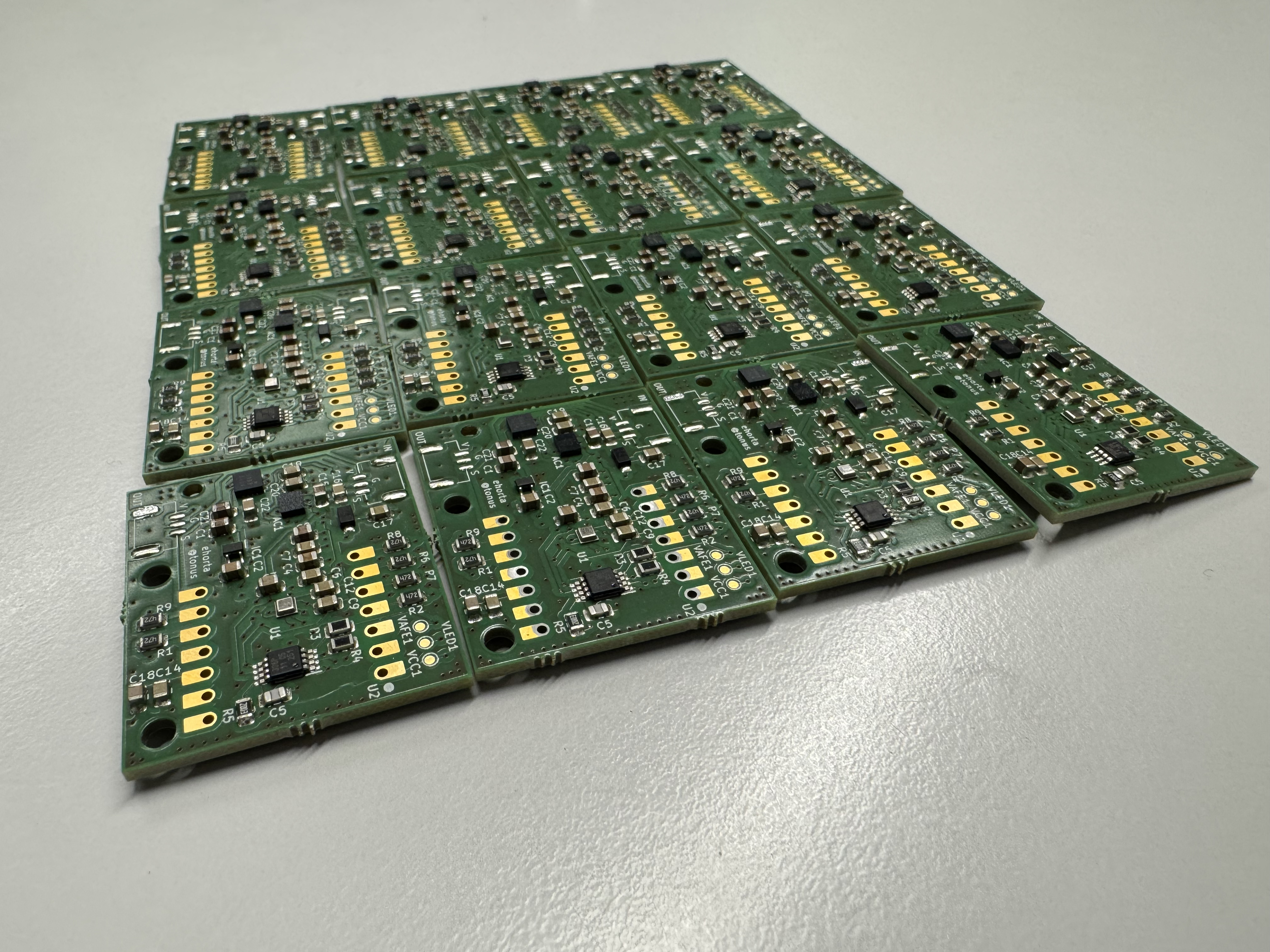
What went wrong with TWD3
TWD3 had three recurring problems.
1. Heat near the optical sensor.
The microcontroller, the radio and the regulators all sat on the same small board as the MAX86916 and the skin-temperature sensor. The board warmed up during operation. For a device that touches skin, this matters twice: the temperature reading no longer reflects the skin, and heat can change the optical contact conditions.
2. Blocked I2C buses.
The optical sensor and the slower support sensors shared I2C. If one device on a shared bus holds the data line low, for example after a brownout or an interrupted transfer, the whole bus stops. In our case a problem with one support sensor could stop the PPG acquisition, which is the one measurement we cannot afford to lose.
3. Sensor dropouts that were hard to trace.
Because everything was on one board and one bus, a missing data stream could have many causes: the sensor, the bus, the power rail, the firmware or the radio. Debugging took much longer than it should have.
All three problems have the same root cause: the measurement path and everything that serves it (compute, radio, power) were not separated. TWD3 was more compact, but harder to trust.
Credit for most if not all the work that went into these two iterations has to given to Etienne Horta Emidio Blüm, who designed, tested and debugged the boards.
What’s next
In Part 3 we show TWD4, our current platform. It splits the module into two PCBs, gives the optical sensor its own protected I2C bus, adds protected power for chaining several modules, and is the first version we built as a full panel.
If you have dealt with I2C bus lock-ups in a mixed-sensor design, we would be interested in how you handled recovery in hardware vs. firmware.
More about TONUS, and how to reach us: tonus.dev
Thanks again to AISLER for manufacturing all of these iterations.
The TONUS team