Intro
Hi from Team Solaride! We’re an Estonian student team building a Cruiser Class solar car for the 2027 Bridgestone World Solar Challenge. This post covers the rear lights, which turned out to be more interesting than “put some LEDs behind plastic.”
Why redesign them?
Last season’s lights did the job, but some of their LEDs cost over €1 each. For this car I wanted each light split into 24 segments of 4–5 LEDs so it could play animations. At the old prices that’s about €100 in LEDs per light, which is hard to justify for a taillight.
There were two other constraints:
- Efficiency. A solar car runs on a tight power budget, so lights shouldn’t waste energy.
- Space. Everything had to fit into roughly 3 cm of height.
How it’s built
Each light has four parts:
- a 3D-printed shell that mounts to the body and holds everything,
- an epoxy diffuser cast into the shell,
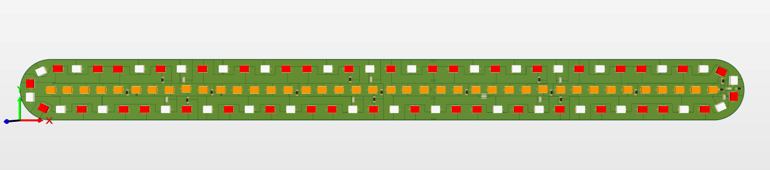
- an LED board with the LEDs and an NTC thermistor,
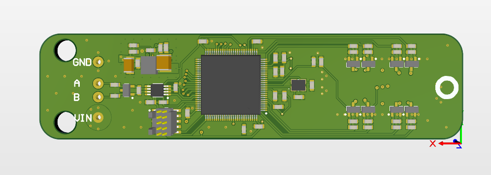
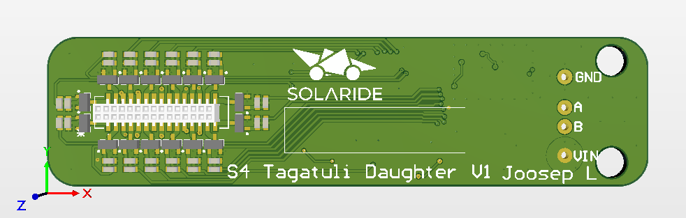
- a driver board connected to the LED board with a connector.
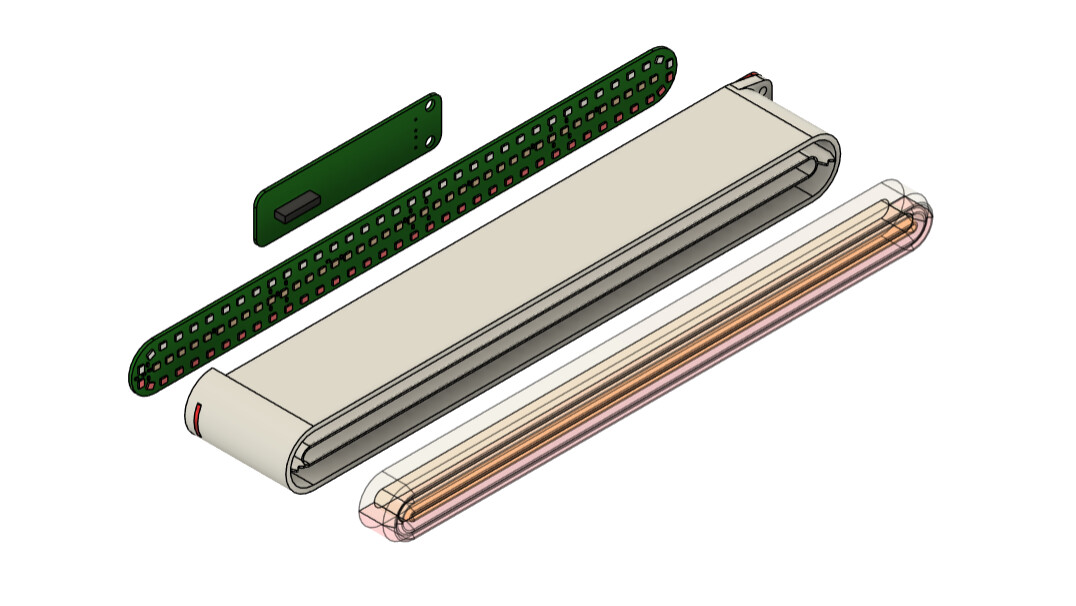
Keeping the LEDs on their own board let me lay it out purely for heat spreading. An aluminium-core PCB was an option, but it would have complicated things more than it helped. The driver board is simple: one MOSFET low-side switch per segment. The thermistor watches the LED board temperature so we can catch thermal runaway before it happens.

LEDs and the case for a humble resistor
After a fair bit of searching we settled on Cree J Series JE2835 LEDs. Colored ones now cost about €0.20 and white ones under €0.10, compared with over €1 before.
For current limiting I skipped dedicated LED drivers and used plain resistors. That’s usually frowned upon, but by picking LEDs whose forward voltage closely matches our supply, the resistor only drops about 5% of the power on the red channels. Testing showed temperatures stay comfortable, and we saved a lot of components and board space.
The diffuser problem
The diffuser has been the hardest part. It needs to hide the individual LEDs and their hotspots, but also let as much light through as possible. Those goals work against each other: more scattering means a smoother look but a dimmer light.
So far I’ve cast epoxy with titanium dioxide mixed in. The ratio is surprisingly touchy: a little too little and you see every LED, a little too much and the light loses a lot of brightness. Next I want to try:
- frosting the outer surface instead of relying only on TiO₂ in the bulk,
- changing the distance between the LEDs and the diffuser,
- adding reflectors around the LEDs to send more light forward.
Things I learned the hard way
Pad size is not a polarity standard. With 5 mm through-hole LEDs, the longer leg is the anode. When my SMD LEDs had one large and one small pad, I assumed the similar logic applied to every LED in that package. It doesn’t, and I found out when my first test only worked with the supply polarity flipped.
Bright LEDs fight back. Debugging lighting is much harder with a collection of purple blobs floating in your vision. A diffuser sample or sunglasses on the bench helps.
What’s next
The lights work and play animations across all 24 segments:
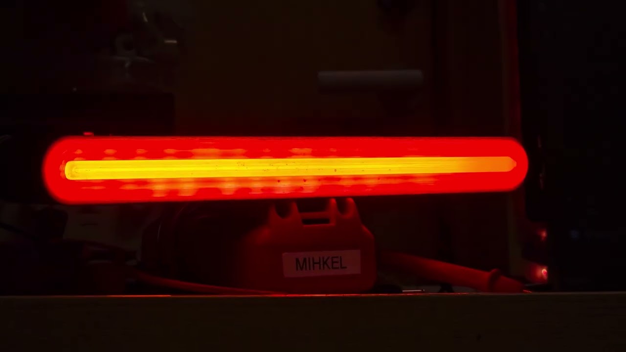
Next we’ll keep improving the diffuser and then fit the lights to the car. We’ll share results when they’re on the road.
Many thanks to Aisler for sponsoring our boards. Quick turnaround and reliable quality make it easy to iterate on projects like this.
See you in Australia!
Team Solaride