What we’re working on
We’re a RoboCupJunior team from Northwest Germany competing in the Rescue Maze category. Our robot has to autonomously explore a maze full of ramps, stairs, speed bumps, and a “Dangerous Zone,” find victims, and deploy rescue kits close to them, all without any human control or pre-mapped information. It’s not about finding the fastest path, it’s about exploring as much of the maze as possible while handling every hazard the field throws at us.
The electronics
Our robot runs on a fairly dense sensor and compute stack:
- Raspberry Pi 5 (8GB RAM) – main brain, handles victim detection via camera
- Teensy 4.0 (with header pins) – low-level sensor fusion and motor control
- 2x RPi Camera modules – victim (letter/cognitive target) detection
- 7x VL53L4CD Time-of-Flight distance sensors – wall following and navigation
- CMPS12 tilt-compensated compass – heading and mapping
- TCS34725 I2C color sensor – detecting blue and black tiles on the floor
- 4x 250:1 Micro Metal Gearmotors HPCB 6V – all-wheel drive
- 2x Feetech FS90 micro servos – rescue kit dropper mechanism
- Custom PCB from AISLER – the backbone of it all
Each component earns its place in the maze rules: the ToF sensors handle wall-following and distance-based navigation, the compass supports heading tracking and mapping, the color sensor catches the blue puddle tiles and black hole tiles we need to react to, the cameras spot victims, and the four independently driven wheels give us the traction to handle ramps, stairs, and rubble in the Dangerous Zone.
Our PCB
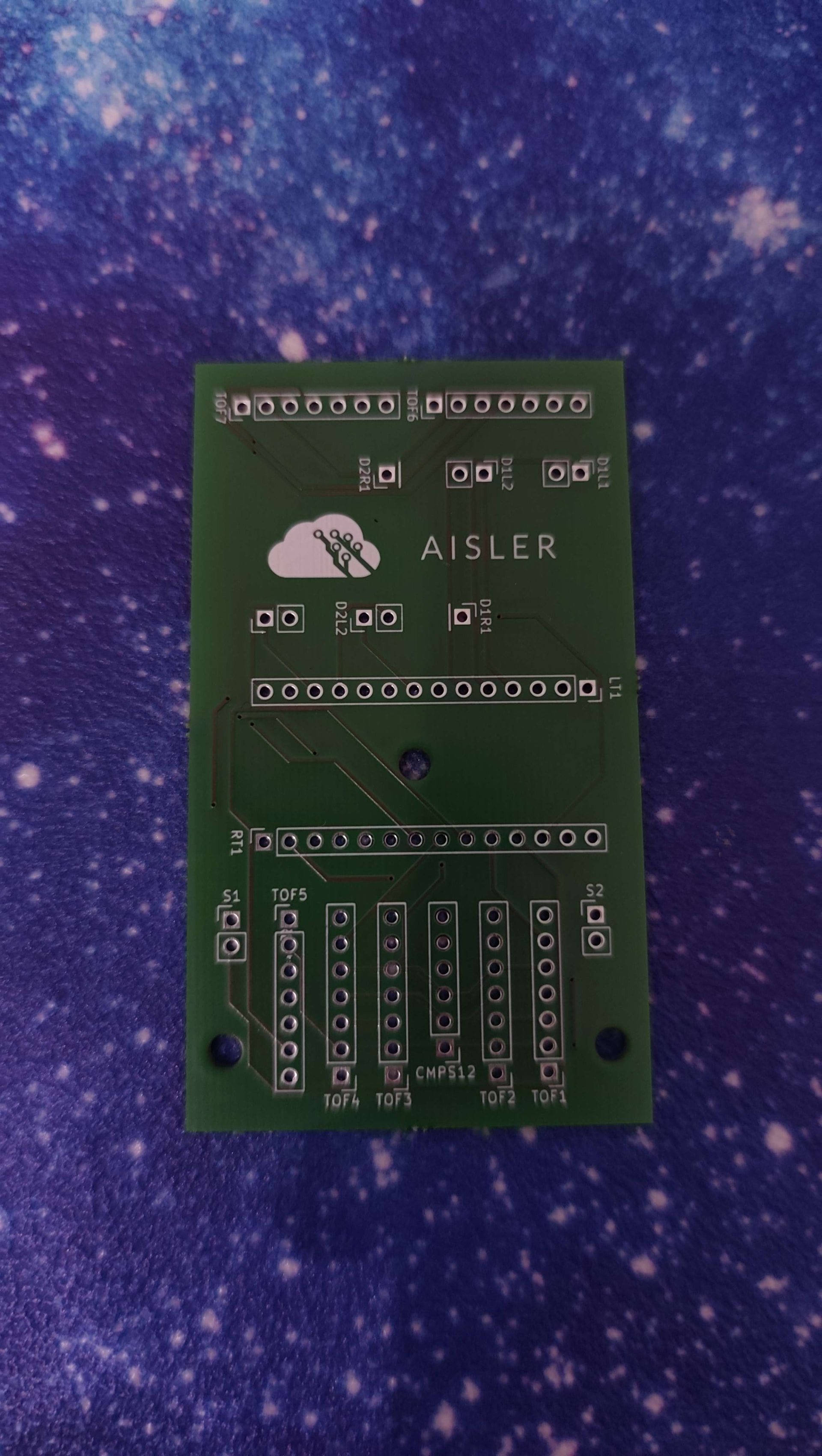
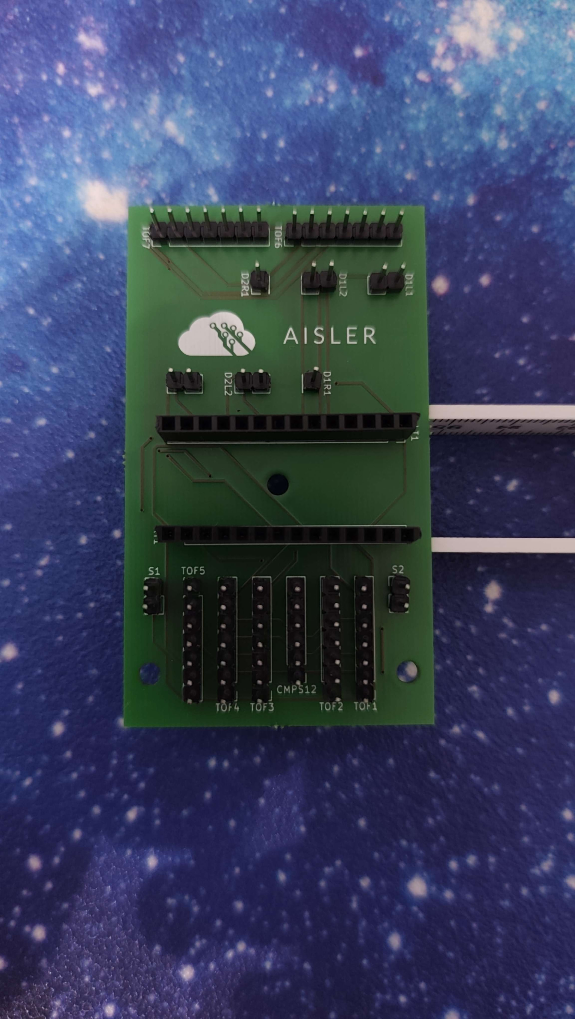
We designed our board in KiCad. It’s a standard, straightforward layout. Its whole job is to act as a clean distribution board connecting our 7 ToF sensors, the Servos, the 4 Motors and the CMPS12 compass to the Teensy 4.0, instead of a mess of jumper wires.
What we learned
This project took us from zero PCB experience to actually designing and ordering our own board. Along the way:
- We went from no electronics background to being comfortable in KiCad and understanding basic PCB design.
- We built the robot chassis ourselves in CAD and 3D-printed it.
- Always have backup modules. We learned this the hard way: both of our motor drivers burned out one day before Competition
- Start earlier than you think you need to. You always have less time than you expect.
What went wrong
Our biggest headache was the ToF sensors, getting the measurements right and actually understanding how to control seven of them properly (addressing, timing, interference between units) took a lot longer than we expected. More generally, just figuring out where to start on a project this size was its own challenge early on.
Our proudest moment
Making it to the German Open in Cologne and taking 2nd place at the Northwest regional cup. Beyond the results, the best moments were the small ones, that feeling when something finally works after you’ve been debugging it for what feels like forever.
Our favorite AISLER feature
Fast shipping: when you’re iterating under competition deadlines, getting boards back quickly matters a lot.
Looking ahead
For next year, we want to redesign our PCB as a ring (or edge-accessible rectangle) shape, so we can connect all our sensors directly to the board around its perimeter and eliminate a lot of our current wiring harness entirely.
Team Ctrl+Alt+Defeat — RoboCupJunior Rescue Maze, Northwest Germany