Introduction
We are FS RTU, a Formula Student team from Riga Technical University in Latvia. Every year, we design and manufacture our own race car, and compete with teams from other universities from all over the world. We are currently in the middle of our third competition season, and this year we are participating in FS Alpe Adria, FS Poland and FSAE Italy.
Our project
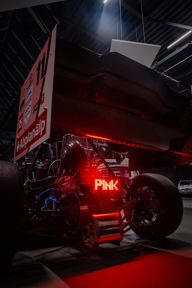
For our 2026 car, we designed several custom electronic systems. Among them is our most visible PCB: the custom brake light at the rear of the car. At first, a brake light sounds like one of the simpler electrical systems on a Formula Student car: apply the brake and make some LEDs light up. Naturally, we found a way to make it more interesting, with a unique LED layout and power electronics to make it as energy-efficient as possible.
Electronics and design
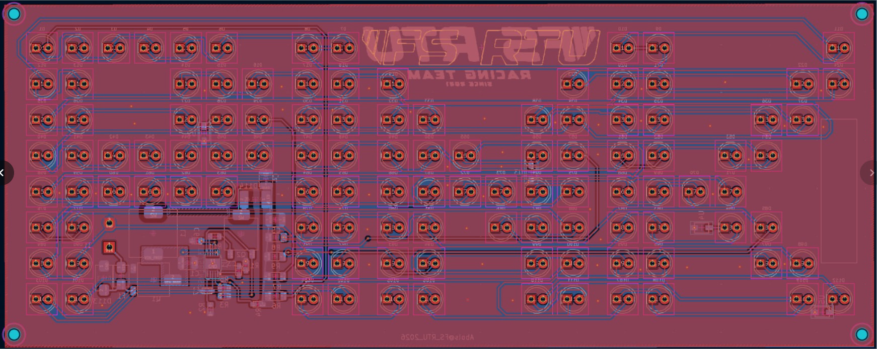
The PCB contains 112 LEDs arranged to spell “PINK”. Instead of simply connecting LEDs and resistors directly to the vehicle supply, the board includes its own power stage and current regulation.
The design was made in KiCad and uses a standard 2 layer, 1.6 mm PCB.
At the heart of the power section is an LT3758 switching controller which allows us to tightly regulate switching boost stage consisting of inductor; mosfet; capacitor and schottky diode for powering the 28 LEDs long strings together with four AL5809-15 constant current regulators before the ground. We also included input protection such as a fuse and TVS diode, because a race car is not exactly the friendliest environment for electronics.
What we learned
One lesson is very simple: design for assembly, not only for the schematic.
When you have more than a hundred LEDs on one board, small decisions about spacing, orientation markings and component placement become very noticeable during assembly.
Another lesson is to think about the environment where the PCB will actually operate. A circuit that works from a laboratory power supply still needs to survive supply variations, electrical noise, vibration and the general abuse that comes with living inside a race car while at the same time not exceeding electrical systems operating envelope’s limits set by the regulations.
And finally: always make the silkscreen clear enough that the person soldering the 100th LED does not have to start questioning which way it goes.
Conclusion
The PCB itself is only a small part of the car, but that is also what makes Formula Student interesting. Seeing something that started as a KiCad project become a real PCB mounted on our Formula Student car is something we are very proud of. And yes, the pink brake light definitely adds at least a few horsepower.
A big thank you to AISLER for helping us turn our PCB designs into real hardware and supporting student engineering projects like ours.
Formula Student is fundamentally about learning by building, testing, occasionally breaking things and then building them better. Having access to professionally manufactured PCBs lets us spend more time doing exactly that.
Greetings from Riga!