Hello,
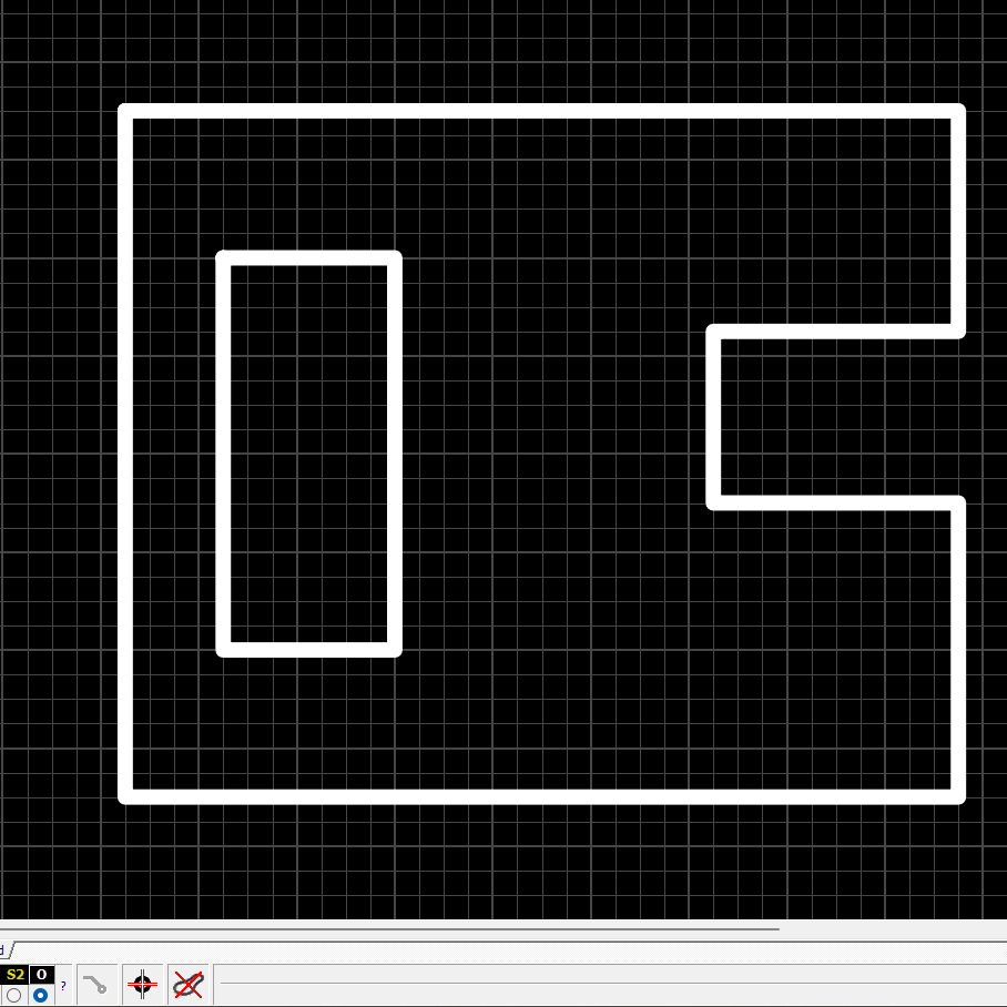
I am using Sprint layout 6.0 and would like to get “rectecgular” cutouts on the 4 endges.
Right now I put big holes on each edge and saw the non wanted parts off.

But I would like to have such an endge contour.

How can I do that ?
Henry
Hi Henry,
I am unsure exactly what you mean by sawing the edge between the holes, did you draw holes and saw the PCB in between them manually?
You should be able to create cutouts and inner cutouts by drawing them on the 0 Layer in Sprint layout. This marks the milling path, please note to keep any copper features 0.3mm away from the edge/cutout.
Yes I tried this, but the Aisler board inspector showed an error because if this ?
I will DM you regarding the project ID.
ok, i tried again. Now it seems to work.
Thank You
WSUKAEGW
It again shows error, but I have no idea what to change ?
The self intersecting board outline error will be displayed if we cannot construct the board outline. This could mean that there is a small stub on the outline, a short open or a radius is off. Another possibility is that Sprint Layout uses short wire stubs in the Gerber file to draw the radii, this is an issue we encounter sporadically with other legacy tooling like EAGLE as well.
Latter one needs to be checked by @Manuel-from-AISLER who implements our CAD tooling.
