Development of a Li-Ion Battery Management System for Formula Student
Hello AISLER community,
we are StarkStrom Augsburg e.V., the Formula Student team of Augsburg University of Applied Sciences in Germany. Every season, students from different engineering disciplines work together to design and build our own electric Formula Student race car.
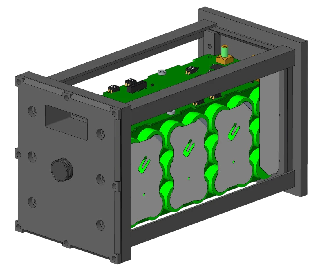
Besides the high-voltage tractive system, the car also needs a reliable low-voltage supply for ECUs, sensors, actuators and other electronic systems. For our current car, we decided to redesign our low-voltage lithium-ion battery and develop our own Battery Management System (BMS).
Why develop our own LV BMS?
One of our main goals with the new design was to integrate more monitoring and diagnostic functions directly into the battery, while at the same time reducing wiring and improving reliability.
The battery uses a 7S3P lithium-ion configuration with 21 cylindrical cells. It has a nominal voltage of 25.2 V and a maximum voltage of 29.4 V.
The BMS continuously monitors the battery and disconnects it from the vehicle if an unsafe condition is detected.
Two-PCB BMS architecture
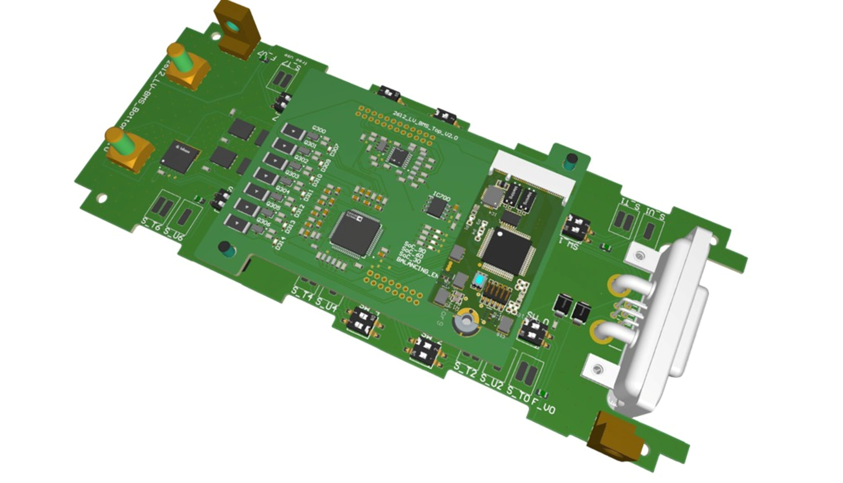
For the new design, we decided to split the electronics into two PCBs.
The bottom PCB is integrated into the main current path of the battery. It contains the battery connections, fuse connection, current sensor, power MOSFETs, gate driver and the circuitry used to disconnect the battery from the vehicle.
The top PCB contains most of the measurement and control electronics, including the battery monitoring IC, temperature measurement circuitry, balancing circuits and our standard StarkStrom processor board.
Splitting the system into two boards helped us keep the high-current section compact and separate it from most of the measurement and control electronics.
Cell monitoring with the LTC6813-1
At the centre of the BMS is an Analog Devices LTC6813-1 battery monitoring IC.
It measures the voltages of all seven series-connected cell groups. Monitoring each cell voltage is important for lithium-ion batteries, as both overvoltage and undervoltage can damage the cells.
The measured values are sent to the microcontroller and evaluated by the BMS software. If one of the configured limits is exceeded, the battery output is switched off.
Temperature monitoring is handled separately. According to the Formula Student rules, at least 30 percent of the cells have to be monitored. With 21 cells in our battery, we therefore measure seven cell temperatures.
Each temperature sensor is mounted directly on the electrically conductive cell terminal. The signals are routed through an analog multiplexer before being measured by the BMS electronics.
Current sensing and power-path protection
Another feature of the new BMS is integrated battery current measurement.
Instead of using a resistive shunt in the main current path, we use a magnetic current sensor. This allows us to measure the total battery current without adding much additional resistance to the power path.
The battery output is switched using low-resistance power MOSFETs. Their temperature is also monitored, which allows us to collect data on the thermal behaviour of the switching stage during vehicle operation.
In addition to the electronic protection, a 30 A main fuse provides overcurrent protection for the battery.
Precharge
Many of the electronic devices connected to the LV system contain relatively large input capacitors. Connecting these directly to the battery can cause high inrush currents.
For this reason, the PCB also includes a precharge circuit consisting of a dedicated MOSFET and a precharge resistor. This allows the downstream capacitances to be charged before the main power MOSFETs are switched on.
The function is currently not required in our vehicle configuration, but having the hardware already integrated gives us more flexibility for future systems.
Passive cell balancing
The BMS hardware also supports passive cell balancing.
The LTC6813-1 controls MOSFETs that discharge individual cell groups through balancing resistors. We also added LEDs so that it is easy to see which balancing channel is active during development and testing.
This allows us to keep the seven series-connected cell groups at a similar state of charge.
In the end, we are very happy to have AISLER supporting StarkStrom Augsburg and our electronics development. For a student team like ours, having access to professional PCB manufacturing makes it much easier to turn our own designs into hardware that can actually be tested and used in the car.
A big thank you to the AISLER team for supporting our Formula Student project!