Things we wish we had known earlier
Sealed 3D-printed enclosures have something deeply satisfying about them. No screws, no connectors, no openings that invite dust or moisture. The device is closed, finished, done.
And then there is the question that tends to be postponed a little too long:
How do we actually update the firmware?
Infrared looks like an elegant answer. No opening required, works through plastic, well understood technology. At first glance, the problem seems solved. In practice, it quickly becomes clear that an IR firmware update is not a pure software feature. It is a system problem — and the PCB plays a much bigger role than one might expect.
The good news: it works
The bad news: it only works under certain conditions
The first test usually goes smoothly. The board sits openly on the desk, the enclosure may not be fully closed yet, the IR sender is carefully aligned. The transfer works, the firmware starts, everything looks fine.
This is also the most forgiving state the device will ever be in.
When the enclosure is finally closed
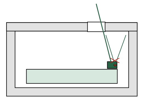
Once the enclosure is fully sealed, the situation changes. The IR receiver now sits behind plastic. The angle is no longer freely adjustable. Ambient light enters the picture. Suddenly, transmission errors appear even though the software has not changed at all.
At this point it becomes obvious: IR is not simply “on” or “off”. There is no clean works or doesn’t work, only more or less margin.
Surprise #1: the PCB defines the update angle
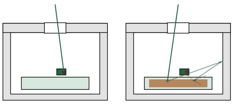
A lot of effort often goes into designing the IR window in the enclosure. Wall thickness, material, surface finish — all carefully considered. What is easy to overlook is that the effective viewing angle is defined by the PCB.
If the board sits slightly tilted inside the enclosure, the IR receiver also looks through the window at an angle. Just a few degrees can significantly reduce reception quality, especially if the sender is not perfectly aligned.
This is not an optical detail. It is a mechanical and electrical decision made in the PCB design.
Surprise #2: copper affects light
Copper pours are almost always welcome in PCB design. More ground, better EMC behavior, cleaner return paths. Near an IR receiver, however, copper can have unexpected side effects.
Large copper areas below or in front of the receiver can change how infrared light is reflected or scattered. In ideal conditions this may go unnoticed. At the edge of reliability, it can remove exactly the margin you were relying on.
Copper may be electrically invisible, but it is not optically neutral.
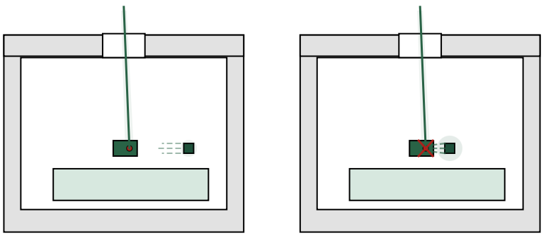
Surprise #3: your own board interferes with reception
Many projects include status LEDs, RGB LEDs, or other fast light sources. What is rarely considered is that LEDs often emit small amounts of infrared light as well. Combined with PWM, this creates periodic disturbances that an IR receiver cannot easily distinguish from real data.
In normal operation this is usually harmless. During a firmware update it can produce exactly the kind of sporadic errors that are difficult to reproduce.
An update mode really needs to be a special mode — on the PCB as well.
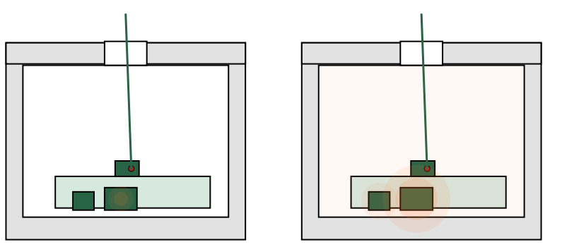
Surprise #4: a firmware update is a thermal edge case
During an update, the device is unusually busy. The CPU runs continuously, flash memory is written, sleep modes are disabled. Inside a sealed plastic enclosure this often results in more heat than during normal operation.
This has consequences. Voltage regulators operate closer to their limits, references drift slightly, plastic expands just a bit. Effects that do not matter in everyday use suddenly appear at the exact moment when stability is most critical.
Surprise #5: the bootloader is the longest-living code
In sealed hardware, the bootloader is not a temporary helper. It is permanent. Errors here cannot be fixed later.
This shifts attention to things that are often treated as details: reset circuitry, flash supply decoupling, brown-out detection. What seems tolerant in normal operation becomes critical in the update path. The bootloader does not forgive unstable power.
Surprise #6: the boot pin suddenly matters more than the firmware
A classic PCB design situation:
The boot or mode pin uses the internal pull-up. Or there is an external pull-up, but it is fairly weak. In everyday operation this works fine. The board boots reliably, nobody thinks about it again.
During a firmware update, the picture changes.
The system runs for a long time, there are more disturbances, more current spikes, more opportunities for resets. If the boot pin is not clearly defined in that moment, a reset may lead the MCU into a completely different boot mode than intended.
The result can be a device that suddenly waits for a programming interface that does not exist, or no longer starts the application. From the outside this looks like a “bricked” device — even though the firmware itself may be perfectly fine.
With open hardware this is annoying but fixable. In a sealed enclosure it is often the end. A clean, dominant pull-up or pull-down on the boot pin is not optional here.
Surprise #7: “almost successful” is the most dangerous state
A failed update sounds bad. In practice, a partially successful update is often worse.
Ninety-nine percent of the data is correct, one block is not. The device boots sometimes, behaves strangely, or crashes after a few minutes. These failures are extremely hard to diagnose — and in sealed hardware, often impossible to recover from.
This is where reset stability, power integrity, and clear update decisions matter. The PCB determines whether an error is detected cleanly or hidden inside undefined behavior.
Surprise #8: updates need an explicit entry point
A device that constantly “listens” for IR is fragile. Ambient light, sunlight, or random IR sources can trigger things nobody intended.
An update should always require a deliberate action: a defined trigger, a timing window, a specific sequence. This is not about convenience. It is part of the safety and robustness of the system.
Surprise #9: the human is part of the system
IR updates are almost always manual. Someone holds a sender in front of a device. Someone waits. Someone gets impatient.
Small movements, changing distances, or aborting too early all look like transmission errors to the firmware. Without clear feedback, the user has no idea whether something important is still happening.
Good feedback is not a gimmick. It is part of a reliable update design.
Surprise #10: the first update is the most dangerous
The first update after sealing the enclosure is often the biggest step. New features, changed memory usage, sometimes even changes in the boot behavior. At the same time, it is the first time the entire update path is exercised under real conditions.
If something goes wrong, it is most likely here — not on the tenth small bugfix.
Conclusion
Firmware updates via infrared in sealed 3D-printed enclosures are absolutely feasible. They are not, however, a pure software problem, nor a small enclosure detail. They are the result of mechanics, electronics, layout, and real-world usage interacting.
If IR updates are treated as a software feature, reality will eventually push back. If they are treated as a system design problem, they can become a surprisingly robust and elegant solution — without openings and without connectors.