This blog post is a follow-up to our previous article about Focus Project Equilibrio. While the first post introduced the robot and the role of electronics in the system, this article focuses on the evolution of our custom PCBs.
In a compact robotic platform like Equilibrio, the electronics are tightly coupled to the mechanical design, power architecture, sensor interfaces, and safety concept. As the robot evolved, the PCBs had to evolve with it.
From First Concept to Power Distribution Board
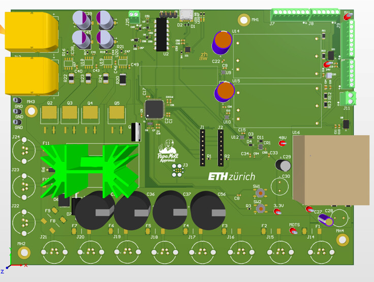
The first PCB revision was developed around the early mechanical concept of the robot. Together with the mechanical team, we defined the available space inside the torso and estimated the electrical requirements of the system, including motors, sensors, embedded computing hardware, and auxiliary electronics.
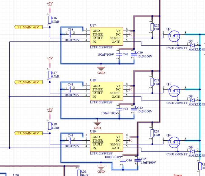
A central part of the design was the power distribution architecture. Since the robot contains several motor controllers with significant DC-link capacitance, the board needed a controlled way to connect the system to the battery. For this reason, the first Power Distribution Board included a MOSFET-based switching concept with a dedicated precharge path.
The switching stages were controlled by gate drivers and supervised by an STM32 microcontroller. This allowed the board to manage different power states, monitor relevant signals, and provide a structured interface between the battery, the actuators, and the rest of the robot electronics.
Iterating the electrical architecture
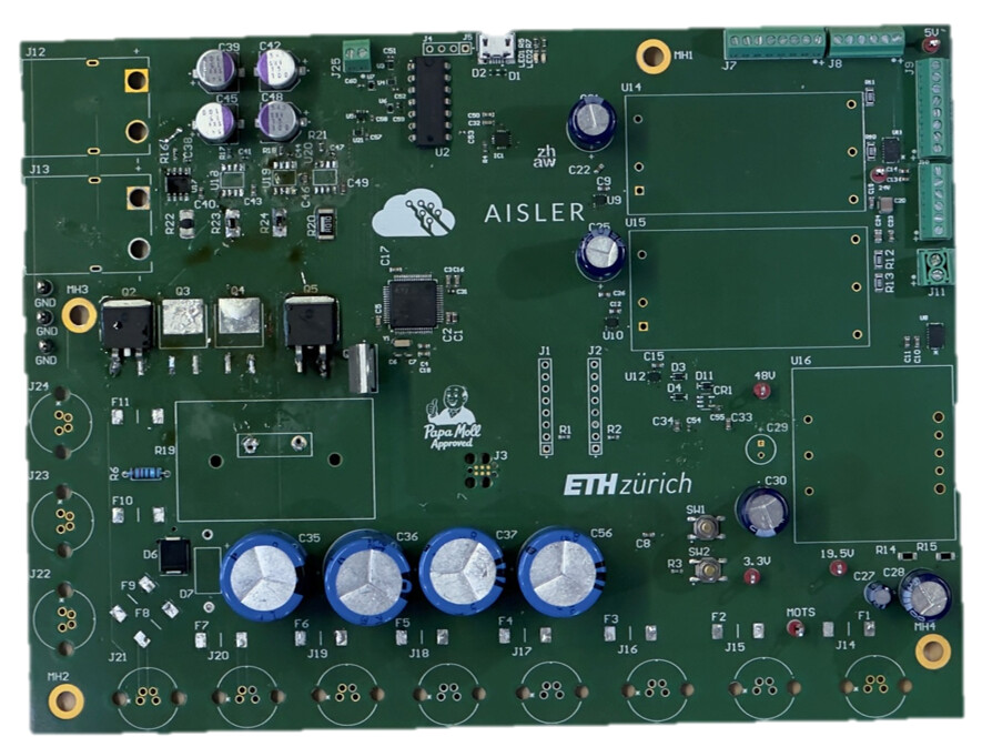
After the first revision, the PCB design was refined to better match the requirements of the robot integration. The schematic was cleaned up, the control electronics were simplified, and several interfaces were adjusted based on the experience gained during assembly and testing.
The second revision also compacted the layout and reduced unnecessary complexity. At this stage, the board was still mainly designed as one integrated electronics platform, combining power distribution, control, monitoring, and auxiliary interfaces on a single PCB.
Moving Towards a Modular PCB Stack
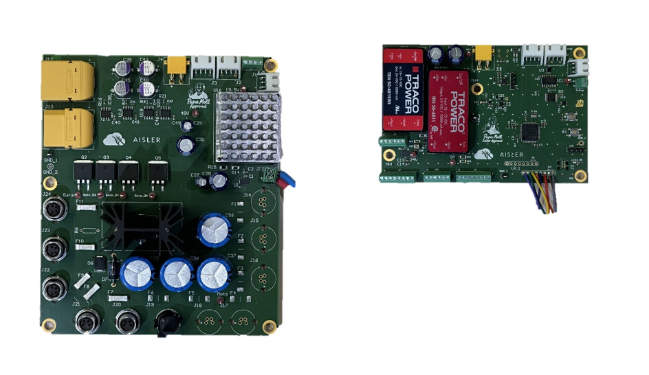
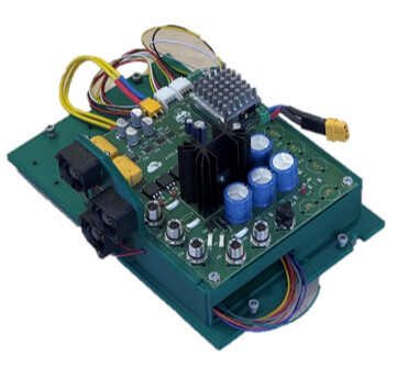
For the final revision, we changed the architecture from one larger board to a modular stack. The system was split into two dedicated PCBs: one board for high-power distribution and switching, and one board for control, monitoring, communication, and low-power conversion.
This separation made the design easier to test, easier to integrate, and more flexible for the available space inside the robot. The two boards were designed with aligned mounting points and connectors, allowing them to be assembled as a compact electronics stack.
The power board handles the high-current paths and switching stages, while the control board provides the microcontroller, signal interfaces, auxiliary power rails, and communication connections. This structure also improves serviceability, since the individual boards can be tested and debugged more independently.
Integration into the Robot
The final PCB stack became the main electronics unit for the current prototype of Equilibrio. It brings together power distribution, control interfaces, safety-related signals, sensor connections, and low-voltage power conversion in a compact form factor.
Because parts of the system operate with high currents and can generate significant heat, the final stack also includes active cooling. Three MagLev fans are used to improve airflow across the thermally critical areas of the electronics.
Why PCB Iteration Matters
For us, PCB manufacturing was not just the last step after finishing a schematic. It was part of the development process itself. Each revision allowed us to turn electrical concepts into real hardware, test them inside the robot, and improve the design based on practical integration experience.
Thanks to Aisler, we were able to manufacture high-quality PCBs throughout the project and iterate quickly on our designs. This support helped us move from early electrical concepts to a compact, testable, and integrated PCB stack for our robot.