Formula USAL Gateway PCB
Hi everybody!
We are Formula USAL, the Formula Student team from the University of Salamanca, Spain.
This is our second year developing an EV, but our first year designing and assembling the vehicle’s electronics completely by ourselves.
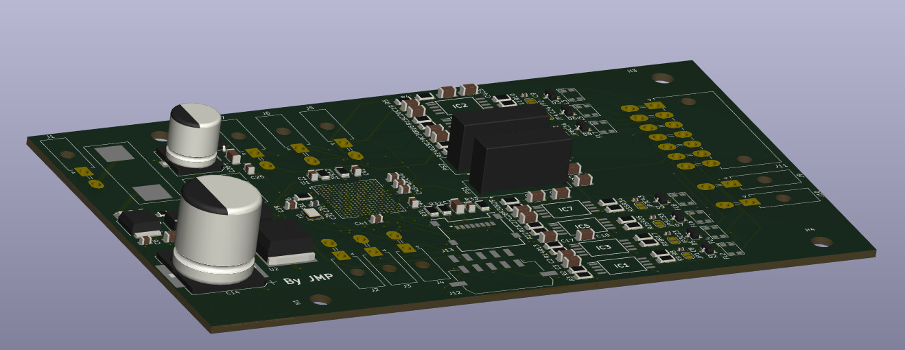
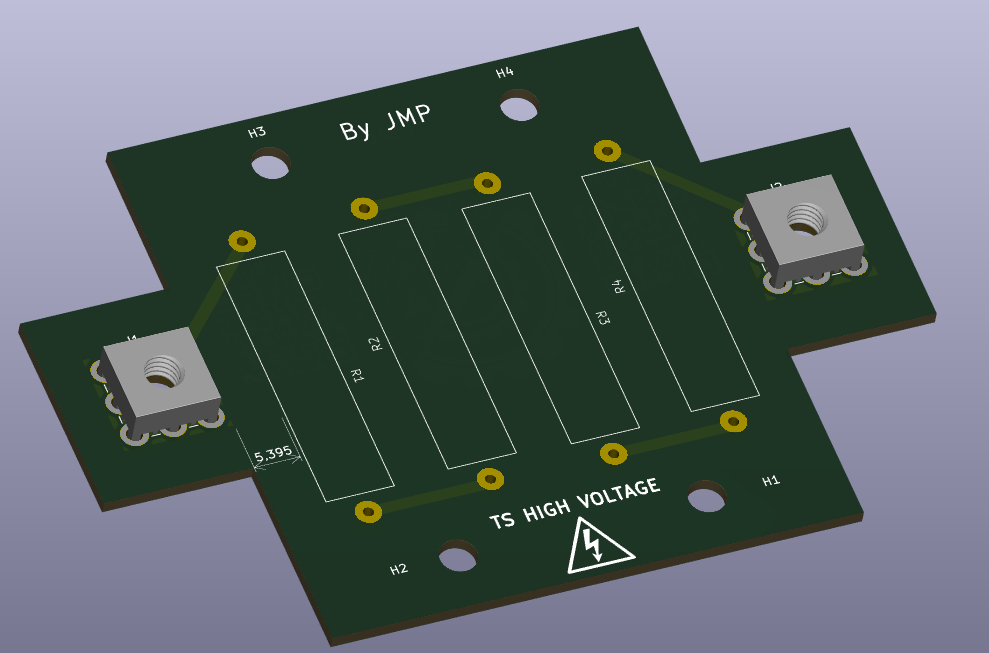
We started the season by developing relatively small boards, such as the TSMPs shown in the third picture. These first PCBs allowed us to gain confidence with schematic design, PCB layout, component selection and assembly. Step by step, this experience has led us to one of our most ambitious electronics projects so far: the development of a six-layer Gateway PCB.
1. Why did we start this project?
Thanks to one of our sponsors, Techlabs Prototypes, we were introduced to CAN communication and its possibilities within a Formula Student vehicle. As the electronic architecture of the car grew, so did the number of ECUs and CAN messages, creating the need for a central point from which the different networks could be accessed and managed.
That is where our Gateway comes in.
The Gateway acts as a central interface between the different CAN buses in the car, allowing CAN messages to be received, processed and forwarded between networks.
In our architecture, we differentiate between signals that are critical to the vehicle’s operation and signals mainly used for telemetry, data acquisition and analysis. Keeping these networks properly organised and isolated was therefore an important requirement from the beginning of the design.
2. Design details
The board has been designed around a microcontroller(S32K8) responsible for processing and routing the CAN messages between the different communication channels.
One of the main challenges was integrating several CAN interfaces into a single PCB while maintaining good signal integrity and separating the different electrical domains. Each CAN channel includes the required CAN transceiver circuitry, filtering, protection and termination-related components, while the PCB layout was developed with particular attention to the routing of the CAN differential pairs.
For this purpose, we implemented a DC-DC conversion stage, together with the corresponding inductors, capacitors, filtering and protection components. The converter reduces the vehicle supply voltage to the lower voltage rails required by the electronics, while the additional regulation stages provide the voltages needed by the CAN transductor.
The power stage was another important part of the project. The board receives power from the vehicle’s 12 V low-voltage system, so this supply has to be converted into the regulated voltages required by the logic and communication circuitry. A 2 stage step down method was used, reducing from 12-5V, and from 5-3.3V in order to supply the microcontroller.
We also use separate power domains for parts of the communication circuitry. This was particularly important because the purpose of the isolation is not only to power the components independently, but also to prevent unwanted ground connections, ground loops and electrical noise from propagating between different sections of the car.
This requirement actually led to one of the most useful mistakes we made during the development of the board.
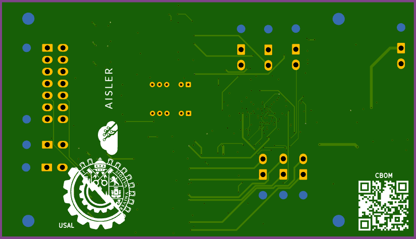
With several CAN channels, power supplies, connectors and protection components integrated on the same PCB, component placement and routing became significantly more challenging than on our previous boards. This is also one of the reasons why we moved towards a six-layer stack-up, giving us more flexibility for signal routing and dedicated power and ground planes.
3. Which PCB design tool do we use and why?
We use KiCad for both schematic and PCB design.
It has allowed us to develop the complete board internally, from the first schematic blocks to component placement, routing and the final manufacturing files. It is also a very useful tool for a Formula Student team because new members can learn the complete PCB development process without being dependent on proprietary software licences.
The AISLER KiCad Plugin makes the manufacturing process even easier. With essentially one click, we can move from the PCB design to the board-ordering process without manually exporting, organising and uploading all the manufacturing files.
For larger or repeated orders, this saves a considerable amount of time and also reduces the possibility of making mistakes when preparing the production files.
Furthermore, the use of folders helps keep everything well organized when a lot of boards are being ordered.
4. What was our greatest failure during the project?
One of our biggest mistakes was accidentally connecting two DC-DC power domains that were intended to remain electrically separated.
The purpose of these supplies was to maintain isolation between different sections of the circuitry. By connecting them together in the PCB design, we effectively defeated part of the isolation that we were trying to achieve.
It was a relatively simple mistake, but also a very useful lesson: galvanic isolation only works if the complete signal and power paths remain isolated, including their grounds.
Finding this problem helped us improve both our schematic-review process and the checks we perform before sending a PCB to manufacturing.
5. What was our greatest win in the project?
Our greatest achievement has been the amount of knowledge we gained during the process.
At the beginning of the season, we were designing relatively simple PCBs. Now, we are dealing with multi-layer boards, CAN communication, power conversion, isolated electrical domains, differential signals and significantly more complex PCB layouts.
More importantly, we have gained experience not only with KiCad and PCB design, but also with component selection, soldering, PCB assembly, debugging and design reviews.
This gives us the knowledge and confidence to develop more of the electronics required by our Formula Student car internally in the coming seasons.
And this is only the beginning.
You are always welcome to visit our workshop!
Feel free to contact us via Instagram or LinkedIn (@formula_usal) and let us know if you would like to come and meet the team.
Formula USAL Team
P.S. If you scan the QR code, you can access the complete BOM/CBOM for the board. Feel free to check out the components we used — some of them might also be useful for your own project!