Hi AISLER community!
We are Formula USAL, a small Formula Student team from Salamanca, Spain. Our team was founded in 2022, and our first competition was FSS 2025. This 2026, we have worked hard in our electronics department to ensure our car is rules-compliant. This season you are going to see us in FSPT in Castelo Branco and in FSS in Barcelona; we hope to see many of you there and chat a bit!
One of the main issues we had these past years was with the temperature monitoring, since the BMS we are using only measures up to 4 cells. The rules clearly state that 30% of the cells must be measured, so we needed to find a solution to measure 14 cells per module. That left us with a total of 140 cells to be measured, but only 40 were actually being monitored.
The solution we came up with was using an STM32 as the brain to read the NTCs. Firstly, we considered using an ESP32, but since these sensors must be placed inside the accumulator, EMC was a concern, and a more robust option was chosen.
A 10-pin connector is placed on the left side of the board, allocating one connection for each NTC to be measured. That signal goes straight into a DIP switch to simulate a fault and display it on a computer during inspections. Since space is also a constraint, a 4-layer PCB is used to reduce the dimensions of the board.
After the switch, a voltage divider is implemented to allow the STM32 to read the sensors. All the signals have decoupling capacitors to reduce noise. Once the microcontroller reads the signals, they are sent via CAN to the AMS, which reads all the temperatures and acts on the SDC accordingly.
The power stage consists of a robust two-stage voltage regulation architecture to efficiently step the 12V supply down to the 3.3V needed by the components. For the first stage, an LM2596S-5 switching buck converter was used, combining it with a 33 µH inductor, an SS54 Schottky diode, and smoothing capacitors to drop the high voltage to a steady +5V without generating excessive heat. Because switching regulators tend to be noisy, this 5V was routed into a second stage featuring an AP2112K-3.3 Low Dropout (LDO) linear regulator. Supported by its stabilizing capacitors, this LDO acts as a polisher, stripping away the switching ripple to deliver a perfectly clean and rock-solid +3.3V supply.
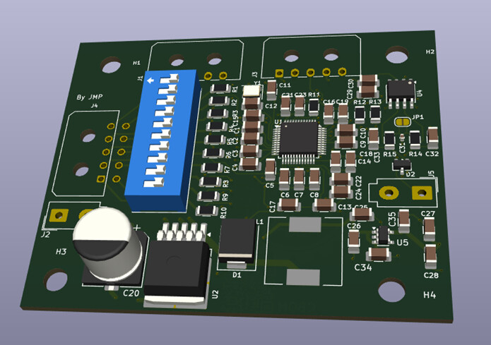
All the connectors used are Molex Mini-Fit or Micro-Fit, due to convenience and price. The CAN part has a split termination resistor, dividing the 120 ohms into 60 on each CAN line. Since the bus is not yet defined, and the design is the same for all the boards on the accumulator, a jumper is used right after the first resistor.
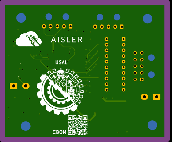
We are very grateful to be able to count on AISLER as our PCB sponsor, and the best things about it are the following:
-
Great communication with the company and a quick response to every problem (Timo, you are the best!).
-
Extremely easy way to order the PCBs and very precise feature detection.
-
The KiCad plugin is wonderful and works perfectly.
-
The extra discount for including the logo is also very helpful to smaller teams with a lower budget.
This is the first 4-layer PCB for the team, and we are very proud of it. Once again, we want to thank AISLER for trusting us with this amazing project that we hope will continue for many more years.