The boardoutline is an essential part of your project, enclosing all your work, ingenuity, and time.
Unfortunately, we often observe that the boardoutline does not receive the attention and care it deserves. In almost all cases, deviations in dimensions and shape can be traced back to problems during the boardoutline detection.
This guide will help you to avoid possible problems in advance.
You have already uploaded a design and we were not able to generate the production data? Then you are also at the right place!
Rule #1: Draw a boardoutline
The boardoutline determines the outer dimension and final shape of your board. We cannot even start processing your data if you do not provide us this essential information. No matter which PCB Design Tool you are using: Your project should contain at least one contour in the corresponding layer, which sets the outline of your PCB.
Although we recommend uploading your project file instead of zipped Gerber, your zip file should of course include one boardoutline file (project_name.boardoutline.ger).
Rule #2: Draw your boardoutline properly
Please ensure to keep an eye on the following points:
a, b) Always close your boardoutline!
c) Avoid multiple elements!
d) Avoid self-intersecting contours!
e) Create a distinct boardoutline!
f) Inner cutouts should not overlap within the outer contour!

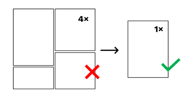
Rule #3: One Design only!
Please note, that we expect to receive the design of one board with one boardoutline. Multiple PCBs lined up together will lead to an error during the processing of your data.
Rule #4: Watch out when using thick lines/arcs
Please note that we convert thick drawn lines and arcs (thickness ≥ 0,45 mm) into a contour. For thinner lines, we set the diameter to zero.

To achieve the best result, draw your board outline with a line thickness of zero!
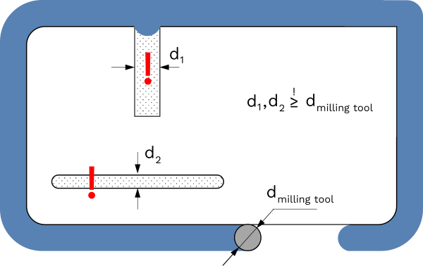
Rule #5: Respect the available milling tools
Please keep in mind, that the realization of convex contours is limited by the diameter of the available milling tools! Notches, slots, and cutouts should have a width / diameter of at least 1.8 mm.
Rule #6: Respect our min. and max. dimensions
Although you are largely free in the shaping of your board, it must comply with the maximum and minimum dimensions. As the boardoutline defines width and height of your PCB, you should keep an eye on that.
