The Academic Space Initiative Switzerland (ARIS) offers invaluable hands-on experience for students passionate about aerospace. Each year, ARIS commits to sending a highly motivated team of students from ETH Zurich and other Swiss universities to the European Rocketry Challenge. This competition not only unites teams from across Europe but also puts their engineering efforts to the test through a series of contests, evaluating various aspects of rocket design and functionality in different competition categories.
HERMES is the 2024/2025 rocketry project of ARIS, building a bi-liquid rocket and launching it in autumn of 2025 to 9km. A first in Swiss student rocketry. This would not be possible without the incredible support of AISLER over the last three years. Their fast and reliable PCB manufacturing allowed us to develop and test many of our PCBs in record time.
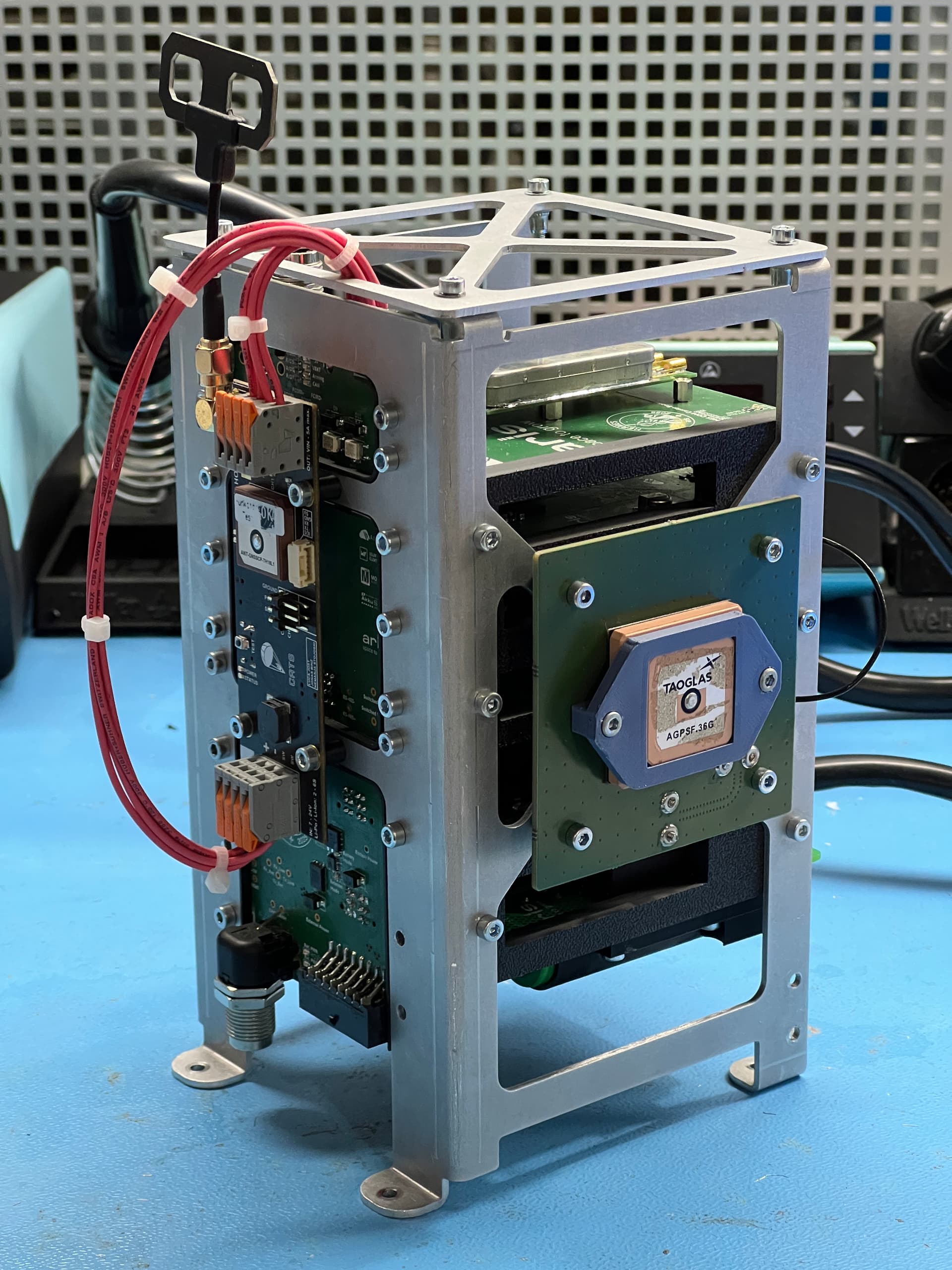
The avionics of our rocket are split into three main parts. The recovery PCB in the top part, the main avionics stack in the upper-center part, and the two pressure control PCBs and one engine control PCB in the bottom part of the rocket. They are all connected by an eight-wire harness (EWSCH), with a circular M12 connector for easy and safe connectivity. This cable supplies power, data over CAN bus and the arming signal to all the PCBs dispersed in the rocket.
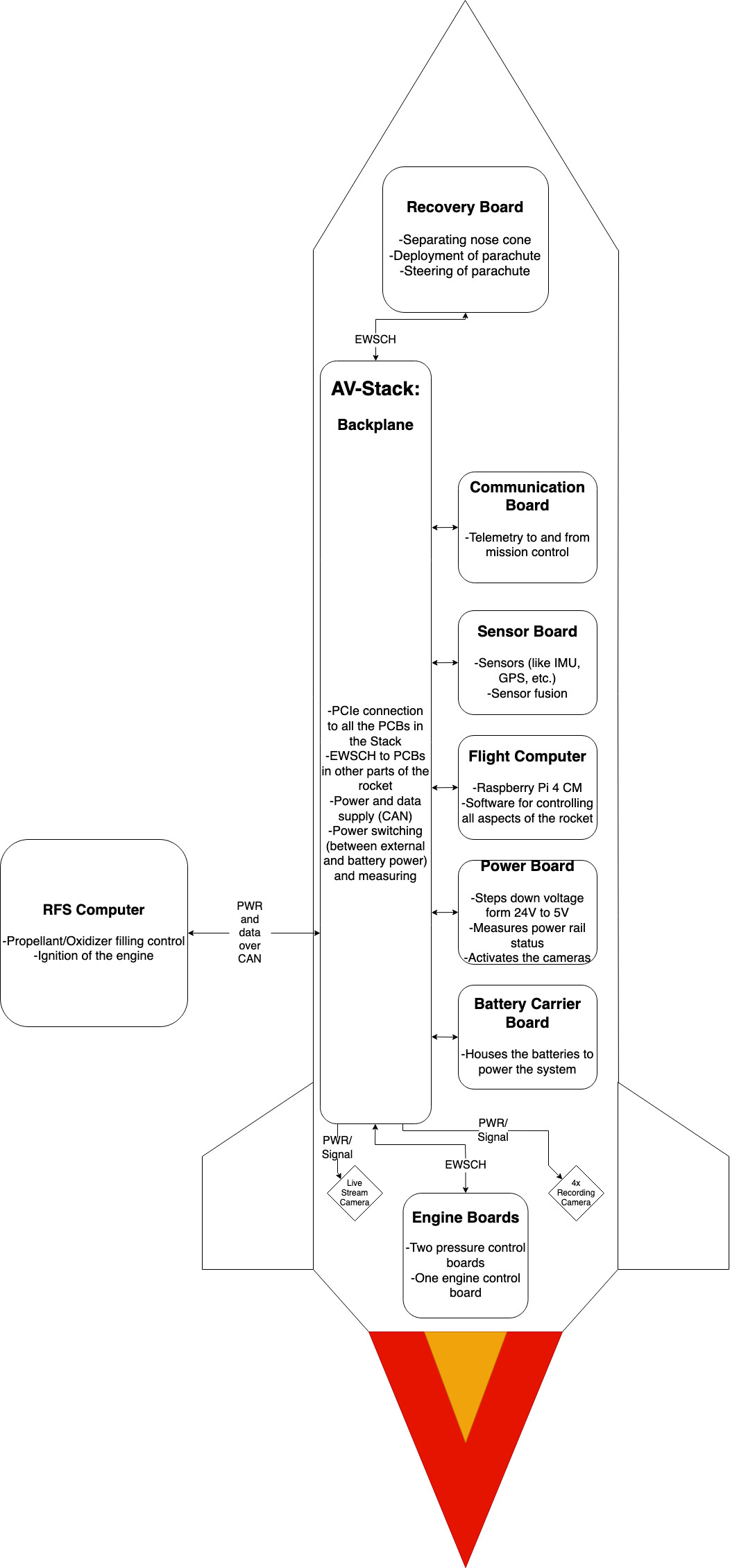
The recovery PCB handles separating our nose cone at apogee, which also deploys our drogue parachute. Later, at the appropriate altitude, the main parachute gets released by the PCB actuating the two redundant deployment servos. We can then steer the main parachute, with the two guidance servos, and execute our guidance, navigation and control algorithm to fly back to a pre-defined landing spot with meters accuracy.
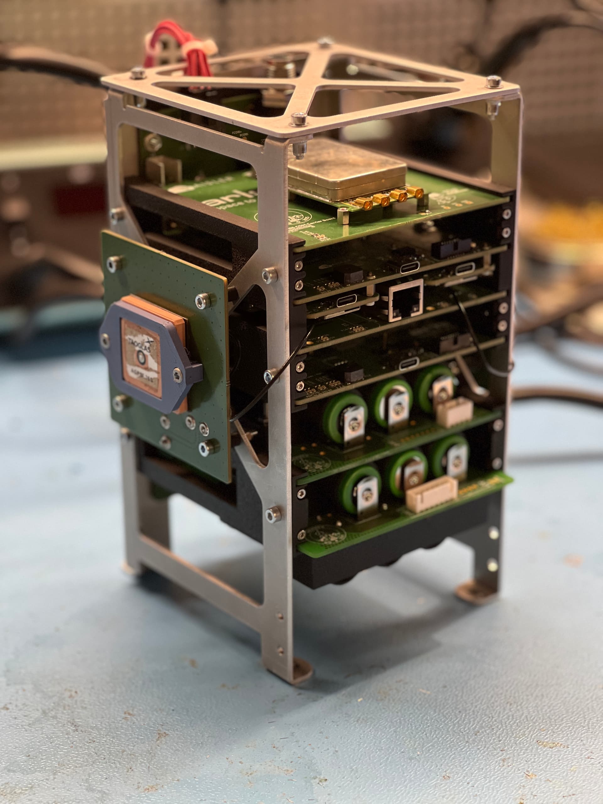
The main avionics stack is composed of seven PCBs all mounted in an aluminum frame. These are the backplane, which connects all the PCBs in the stack and then from top to bottom, the communication PCB, the sensor PCB, the flight computer PCB, the power PCB, and two battery PCBs.
The backplane delivers power and CAN bus connection to each PCB, and connects to the PCBs outside the stack via the EWSCH. This structure allows us to quickly slide PCBs in and out of the stack to change them. It also is connected to the remote filling station to get external power while still on the launch pad and communicate with the filling computer during the filling of the rocket.
The communications board has been completely redesigned from scratch this year. Over a 2.4GHz LoRa connection, it allows us to communicate between our flight computer and our mission control system. It sends the status of the system, which includes sensor data and the flight computers state, to mission control and from there we can also send manual commands or aborts, if something does not go as planned.
The sensor board handles data acquisition for positioning and heading. It includes two STMicroelectronics LSM6DSO32TR Inertial Measurement Units (IMUs), two TE Connectivity MS560702BA03-50 barometers, two Sensirion SHT40A-AW1B-R2 temperature and humidity sensors, two STMicroelectronics LSM303AGRTR magnetometers, and two u-blox ZED-F9P GNSS modules. Each sensor is redundant, and a sensor pair is never on the same bus, to always ensure reliable data. We further run a Kalman filter on an STM32H7 to fuse the data from the different sensors together and get accurate position and heading data for our guidance system. This then gets transmitted to the flight computer. Additionally, we log the sensor data on both a flash chip and a micro-SD card for post flight analysis and tuning of the sensor fusion.
The flight computer is similar to the one we used last year, so if you are interested in more information about it, you can read the post named “Rocket Flight Computer -NICOLLIER” in this forum.
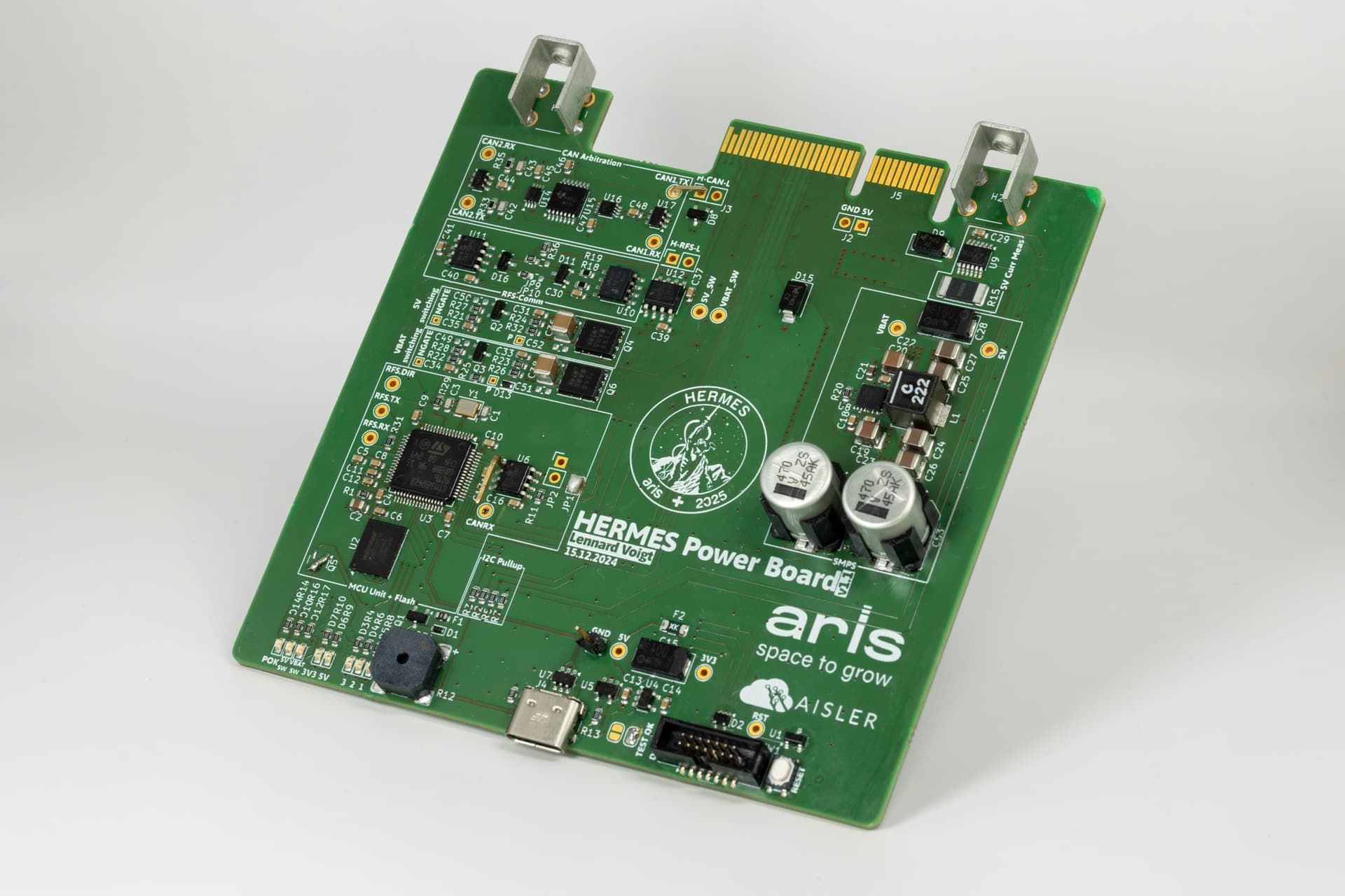
We further have a power board, which converts the 18-26V from battery and external power to 5V for the electronics with a switch mode power supply. It is also able to switch on and off the power to our four recording and one life streaming camera dispersed through the rocket. Additionally, it features a CAN isolator to connect the remote filling station computer to the CAN bus of the rocket, while also being able to disconnect it when the rocket takes off, without breaking the CAN bus.
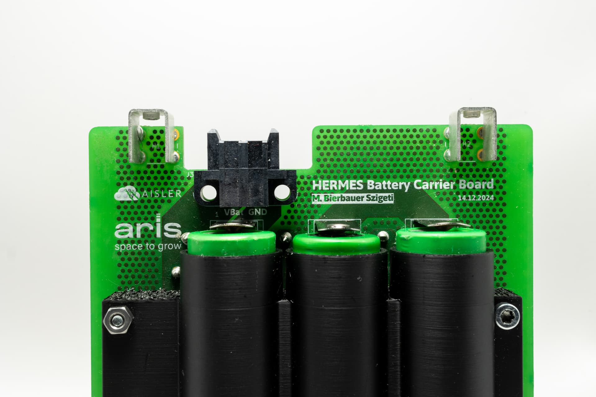
Another completely new system this year is our battery carrier PCB. As the name implies, these carry our batteries and supply our rocket with power. They are connected using a Samtec MPS connector and can, like the other PCBs in the stack, easily slide into the stack and connect in a matter of seconds. They also feature balancing connectors to charge the cells without taking them off the PCB. We have two of them, one powering the main electronics of the rocket, having six cells and running on 24V and a second one with only three cells, to save weight, supplying the backup flight computer with 12V.
On the back of the AV stack is our CATS VEGA back up flight computer. This is a redundant commercial-off-the-shelf flight computer that can separate the nose cone and deploy our parachute in case of a failure of our main system.
In the bottom part of the rocket are two pressure control PCBs and an engine control PCB. These regulate the plumbing, which supplies our engine, and control the correct amounts of fuel and oxidizer flow into our engine.
Additionally, to the electronics inside the rocket there are also critical systems outside the rocket, like our remote filling station (RFS) and mission control. The remote filling station handles filling the rocket with the nitrogen needed for pressurization and liquid oxygen, which we use as oxidizer, for the engine, without human intervention. This is necessary as, in the filling process and afterwards, no one can access the rocket anymore for safety reasons.
Our team is incredibly grateful and proud to have AISLER support us for the last three years and allow us to reach new heights. They manufactured many of our PCBs, fast and reliable every time. We look forward to many more years of working with them.