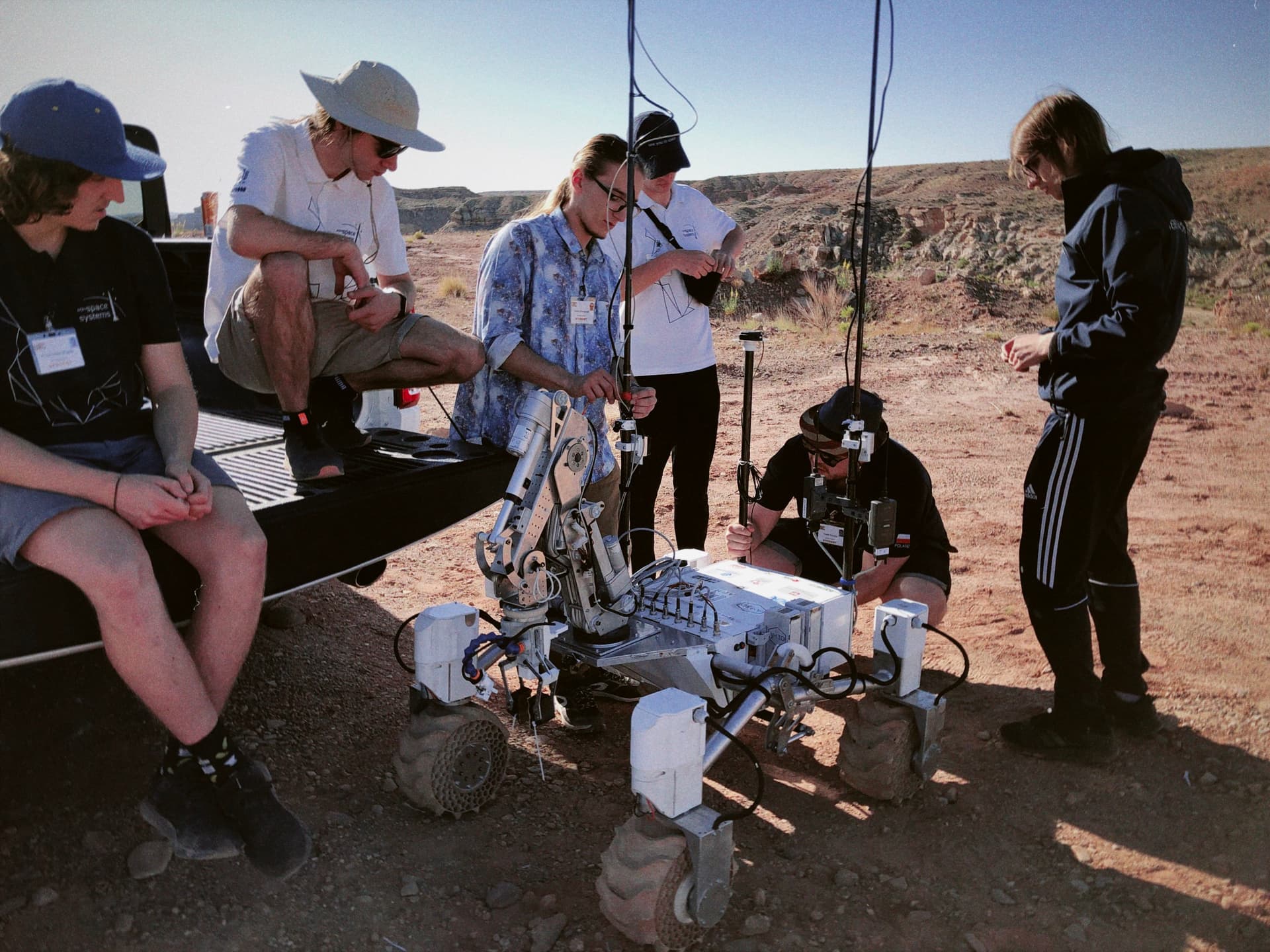
As the planetary rover team of AGH Space Systems, we wanted to share with you some electronic projects that we have recently created during the preparations for the University Rover Challenge 2022 competition that took place in the USA. We will probably need to share a few posts with you to show all the cool new stuff we got inside our rover. As said, today, as an introduction, we will talk a little bit about our standardised “mini Rack” system and how we significantly have improved our workflow using Altium Designer project templates. Drawing all the conclusions from the previous rover competition - European Rover Challenge 2021 that took place in Kielce, Poland - we have decided to almost completely redesign half of our electronics.
Our goal was mainly to improve the vision system and make our new designs more consistent and easy to implement. Here comes the idea of designing a new standardised rack system. To achieve this goal, our team started using the Altium Designer template for creating new boards with defined board outlines and already populated essential parts like the CAN transceiver, eFuse/Hot-Swap circuit, and the connector for our “miniRack BUS”. By using this solution we have saved a lot of time on creating new sub-modules for our design. Especially we found out how helpful the project templates and Aisler fast services were when we needed to design and manufacture PCBs at the very last minute before departing to the USA.
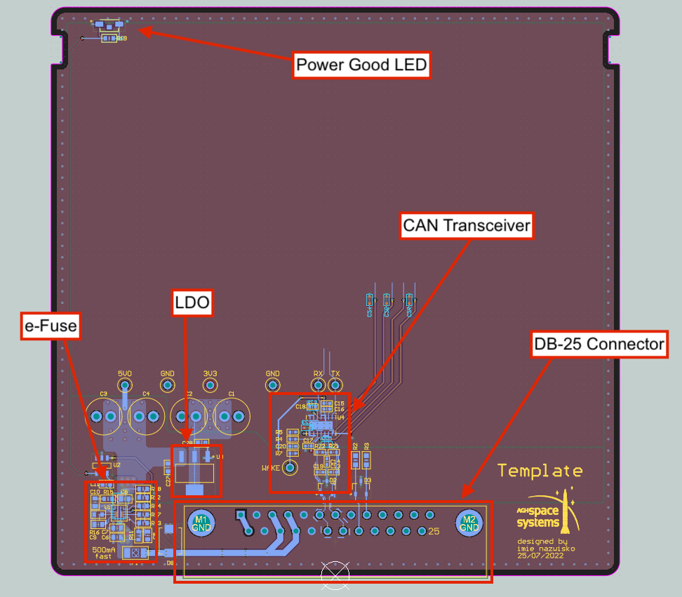
The picture above shows our Altium Designer template and what is already included when we start a new project. The eFuse IC is TPS25947, which helps us not to blow up our boards ![]() . It protects the board against inrush current, over current, short-circuits, over voltage, under voltage and reverse polarity. Although it’s a very small IC, it is very functional. It also makes our boards safely hot-swappable. Just right behind the protection circuit we have a simple LM1117 linear regulator which steps down the voltage from 5V to 3.3V for MCU and other ICs.
. It protects the board against inrush current, over current, short-circuits, over voltage, under voltage and reverse polarity. Although it’s a very small IC, it is very functional. It also makes our boards safely hot-swappable. Just right behind the protection circuit we have a simple LM1117 linear regulator which steps down the voltage from 5V to 3.3V for MCU and other ICs.
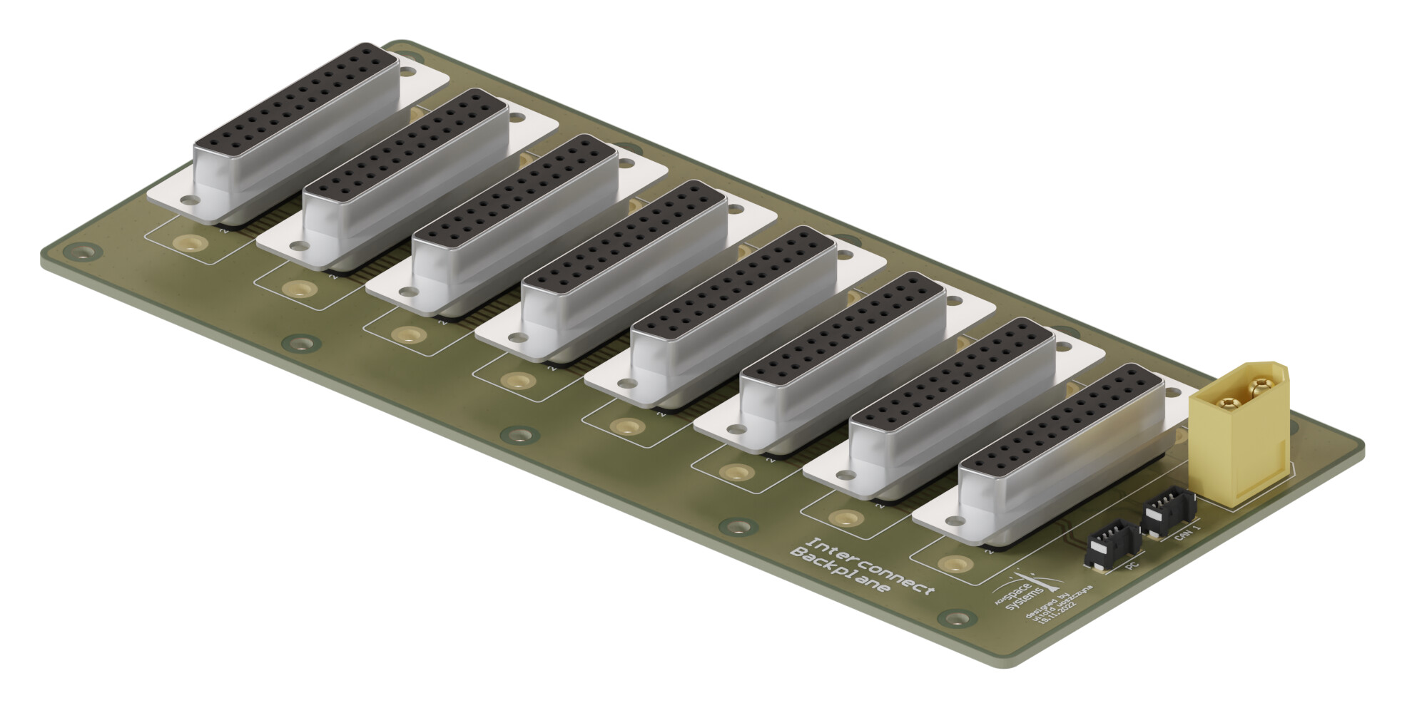
Our initial idea was to connect all the modules with the backplane using PCB edge connectors - very similar to those used in PCs. However, in the end, due to our doubts about the continuity of the connection during vibrations, the durability and wear of contacts on the PCB, we finally decided to choose a different solution. In our design, every board is plugged into a backplane board using D-Sub DB25 connector, which we find to be the best solution providing our system robust connection at quite low cost.
In “miniRack BUS” we have included two voltage rails - 24V and 5V. 5V is used to power all the electronics placed on each module, like CAN, MCU, etc., where 24V is needed for the Buck converter module (which provides 5V to the Bus) and for other devices that are connected to these modules - i.e. analog cameras connected to “Analog Vision MUX” or 433MHz radio modems connected to “Master”. All the modules are connected by the CAN Bus. We also decided to put some spare signal traces that are not used at the moment just in case we wanted to implement additional features in the future. There are also two signals for turning on and restarting the PC responsible for running autonomous navigation tasks that we face during the rover competition.