
After the European Rover Challenge 2021 in which we took 4th place, we decided to redesign the vision system in our rover - Kalman . In the past, we were using PoE IP cameras connected to the router and the video was streamed through the WiFi network. This setup had an advantage of better image quality over the analog system, but it was heavy, the latency was too high for the precise control of the rover and last but not least the operating range was much shorter. In November 2021 we decided to completely remove the IP camera system and replace it with an analog one.
An advantage of the IP system was that we could just connect as many cameras as we wanted and switch between them in our ground station. With the analog system this was a little more complicated because we decided to have two 5.8GHz radio transmitters on the board of the rover and use at least 6 cameras. To achieve our goal we designed a custom multiplexer circuit that can switch camera output video signals between two video transmitters.
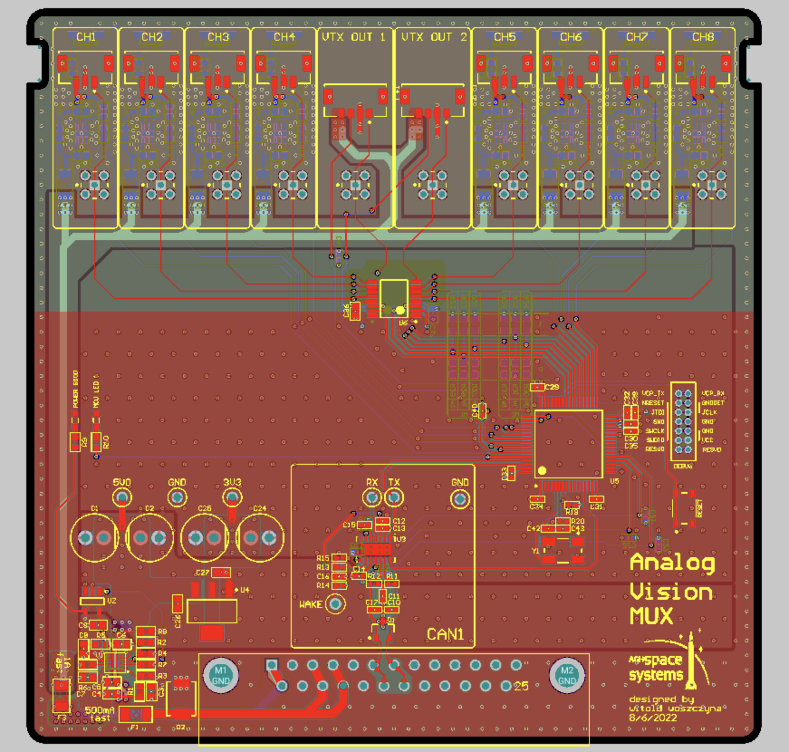
Our solution is a board that has the ability to pass any of the eight input channels into “VTX OUT 1” or “VTX OUT 2” . For that purpose, we use two DG408, 8 channel single-ended analog multiplexers designed to connect one of eight inputs to the common output - one located on top layer and the second one on bottom layer. The MUXes are controlled by an STM32G474 microcontroller which receives commands from our rover’s CAN bus. Another cool feature is that the MCU has the ability to send commands to VTX modules which are responsible for changing the frequency at which video signal is transmitted on the go as well as output the power from 25mW up to 1W. This feature is very useful in the competition when another team by mistake starts transmitting video on the same channel as us, as it causes jamming our vision, or if we want to increase the RF range.
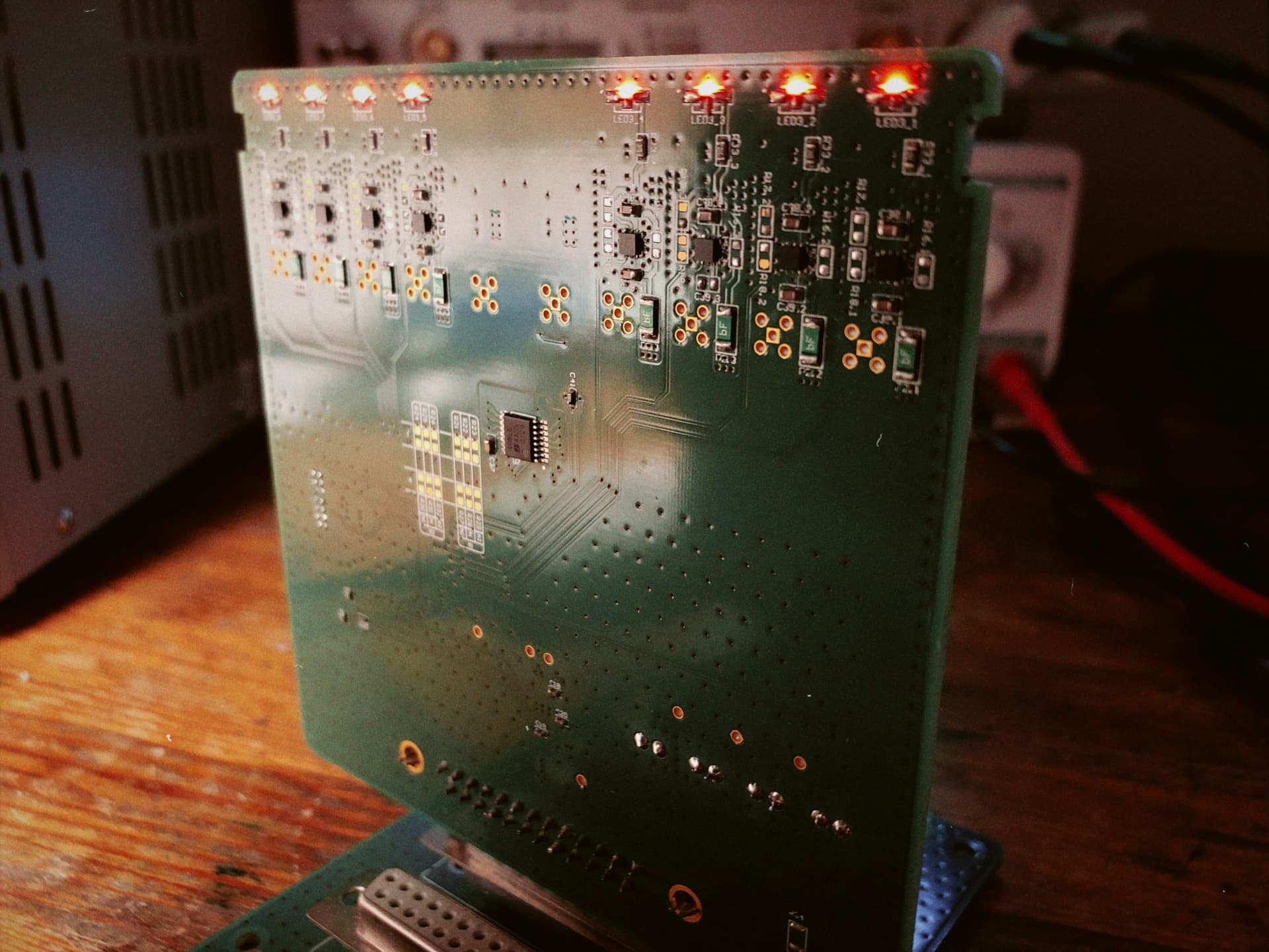
Fused 24V is directly used to power transmitters as they are 36V input voltage rated devices and for analog cameras the voltage is stepped down to 22V by LDO linear regulators for each channel. This solution was intended to add a little margin to 24V input voltage rated cameras and to gain the ability to turn off the power supply. For that purpose we chose NCP730, an adjustable linear regulator with maximum input voltage range of 36V. By driving an ‘EN’ pin we can turn on or off the selected cameras.
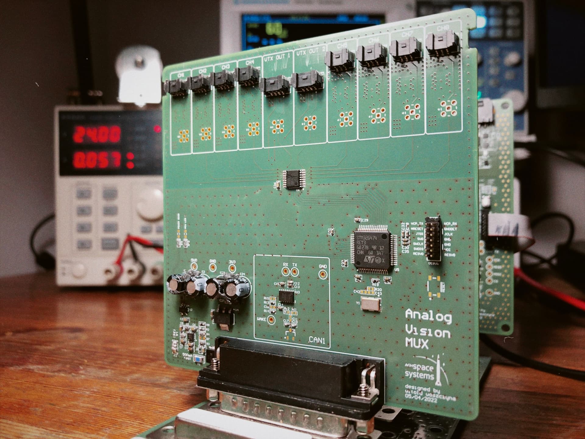
This project couldn’t have been executed without Aisler’s support in the form of producing the PCB board for us. We are extremely grateful to cooperate with such professionals!