Abstract
This circuit appnote describes how users can implement USB2.0 devices (UFP) in accordance with the USB-C specification.
Introduction
Previous USB generations typically determined the Power and Data role through physically different types of connectors. Type-A as Source/Host and Type-B as Sink/Device. With USB-C, the USB Implementers Forum introduced a new connector type which does not have predetermined roles and is reversible.
The USB-C spec is quite complex and documents many additional features, but these are beyond the scope of this circuit node. We will focus on a USB 2.0 Device such as a Keyboard or USB to Serial bridge that can use up to 500mA current, also referred to as upstream facing device (UFP) in the specification.
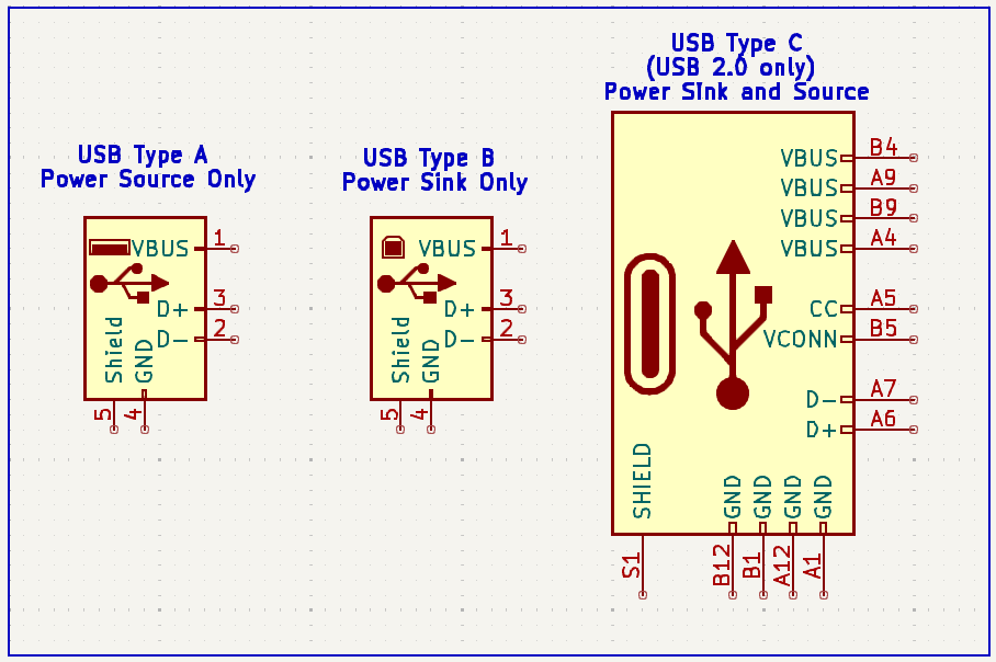
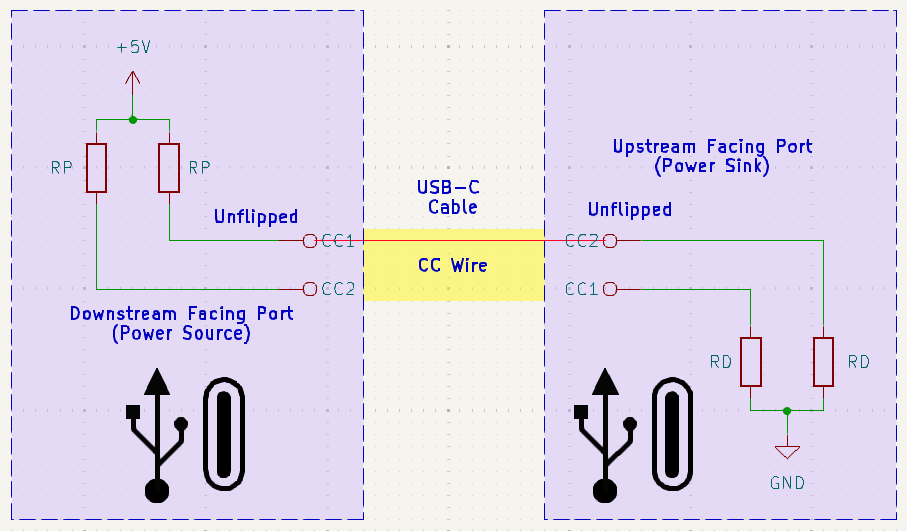
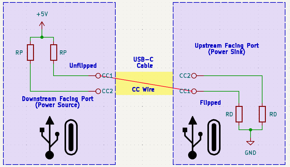
As the power roles are not set by the connector type, and thus it is required to determine them upon making a connection. This is done via the CC signal, CC stands for configuration channel and is used to determine the cable orientation, basic current advertisements, attachment as well as removal detection.
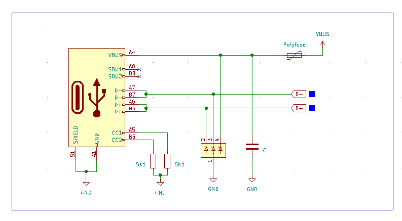
Downstream facing ports use a pull-up resistor or current source, Upstream facing ports a pull-down resistor or current sink. Together, they form a voltage divider, the resulting voltage is corresponding to the current the Downstream facing port can deliver. For a UFP device, a 5.1kΩ pull-down resistor to ground must be placed on each CC pin (CC1 and CC2). This signals to the host that a device is attached.
Furthermore, pins sharing the same function must be tied together on the PCB. Tie all VBUS pins together, tie both D+ pins together, and tie both D- pins together. A 1µF to 4.7µF decoupling capacitor must be placed between VBUS and GND, positioned as close to the connector as possible to limit inrush current. ESD protection for the data lines, as well as VBUS, is highly recommended.
Basic Implementation
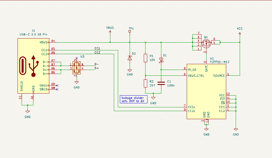
Additional Protection
Due to the wide range of non-compliant USB-C devices such as chargers that output a voltage greater than 5V without USB PD negotiation, it is desirable to add additional protection such as overvoltage protection and ESD protection. The TCPP01-M12 from ST adds VBUS overvoltage protection, which can be set by an external voltage divider and ESD protection for the CC data lines.
If an overvoltage event is triggered, the TCPP01-M12 turns off the N-Channel MOSFET. An additional ESD diode is used for the USB data lines.
IMPORTANT NOTICE
AISLER assumes no liability for design assistance provided by this appnote. Engineers/designers are responsible for their design.