The USB-C specification defines a “universal” reversible connector which allows higher data/ power throughput compared to the traditional connectors, this post details the best practices for implementing a Type-C connector with USB2.0 connectivity which is sufficient for most projects.
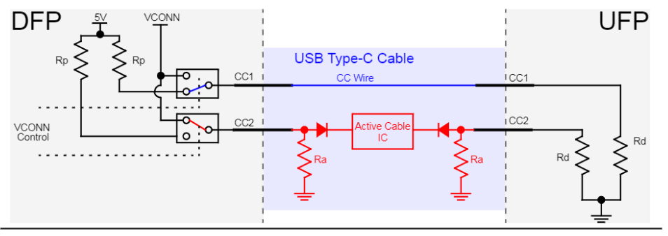
USB C cables carry additional signals (VCONN/CC) compared to the older USB A/B cables.
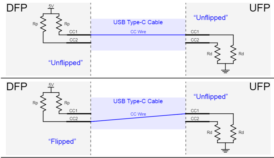
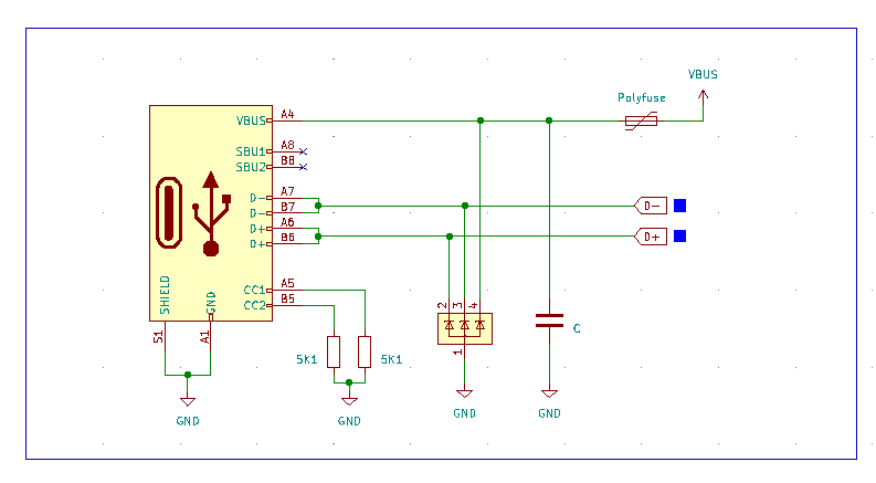
CC stands for configuration channel and is used to determine the cable orientation, basic current advertisements, attachment as well as removal detection.
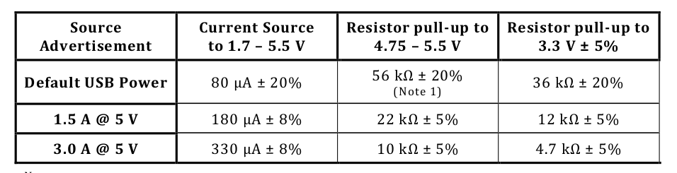
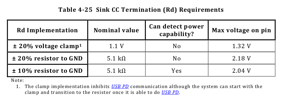
Downstream facing ports feature a pullup resistor or current source, Upstream facing ports a pulldown resistor or current sink. Together they form a voltage divider, the resulting voltage is corresponding to the current the Downstream facing port is able to deliver. For the simple USB 2.0 breakout a 5K1 resistor on each CC pin is sufficient. It is important to have separate resistors for each pin!
Using one shared pulldown for both pins would cause issues with electrically marked cables. As as the 800R to 1K2 Pulldowns on the CC2/VCONN connection would be in parallel with the 5K1 Pulldown and thus no valid configuration is possible anymore.
Furthermore it is necessary to connect all pins with the same nets like VBUS, D+ and D- together. A 1u-4u7 capacitor should be placed close to the connector. ESD protection for the data lines as well as VBUS is highly recommended.
good day, im following the topic of the usb c connector… but i don’t understand why in some designs they are not using the, 5.1k resistors… what the reference for the diode must be use for D+ and D-
Take a look at this introduction from Microchip. The 5.1k resistors are needed to enable more current flow. If you don’t use them only 500mA are possible.
Section 3.2: “A 5.1kΩ ± 10% is the only acceptable resistor if USB Type-C charging of 1.5A@5V or 3.0A@5V is to be used.”
hello, thank you for the info datasheet you sent me, on my usb type c ive add on D+/D- lines two 200ohm resistors, but i would like know what is the reference diode I can use.
I assume you mean 20 Ohm? Thats a common value for USB Low and Fullspeed devices. You usually add them to the design if the USB PHY inside the MCU has a Impedance missmatch, dont add them if the vendor doesnt reccomend them.
The diodes are TVS diodes to prevent the device downstream from voltage spikes, I will share a list in this thread soon.
Yes sorry… 20 Ohm resistors, im working on a flight controller equipped with an H7 a G491 MCU, so i think to remove the resisstors and keep only the TVS diode
The CC pulldown resistors are required, without them the source doesnt turn on VBUS.
Quoting the USB-C specification:
2.3.1 Source-to-Sink Attach/Detach Detection
Initially, Source-to-Sink attach is detected by a host or hub port (Source) when one of the CC
pins at its USB Type-C receptacle senses a specified resistance to GND. Subsequently,
Source-to-Sink detach is detected when the CC pin that was terminated at its USB Type-C
receptacle is no longer terminated to GND.
Power is not applied to the USB Type-C host or hub receptacle (VBUS or VCONN) until the
Source detects the presence of an attached device (Sink) port. When a Source-to-Sink attach
is detected, the Source is expected to enable power to the receptacle and proceed to normal
USB operation with the attached device. When a Source-to-Sink detach is detected, the port
sourcing VBUS removes power.