
MOBeFuse: Testing eFuses for CubeSats in Orbit
MOBeFuse is SeeSat e.V.’s in-orbit experiment to evaluate compact commercial electronic fuses (eFuses) for CubeSat power distribution , a smart, space-saving alternative to traditional Latching Current Limiters (LCLs). The project validates their protection functions and reliability under real Low Earth Orbit (LEO) conditions.
Project Context
SeeSat e.V., based in Friedrichshafen (Germany), develops an Electrical Power System (EPS) for our ERWIN CubeSat, a mission for wildfire detection from orbit. The MOBeFuse experiment tests Commercial-Off-The-Shelf (COTS) eFuses as a compact alternative for discrete LCLs. The experiment investigates how their protection characteristics perform in the harsh space environment, including temperature extremes and radiation, and provides reliability data for student missions and NewSpace applications.
Background:
Latching Current Limiters (LCLs) are commonly used to safeguard satellite subsystems against damage caused by Single Event Effects (SEE). Modern eFuses, implemented as integrated circuits, offer a compact and configurable alternative but lack comprehensive in-orbit data. MOBeFuse addresses this gap by testing both a commercial eFuse IC and a custom-built current limiter under actual LEO conditions to raise their Technology Readiness Level (TRL) for future satellite applications.
Objectives
-
Raise the Technology Readiness Level (TRL) of eFuses via in-orbit validation.
-
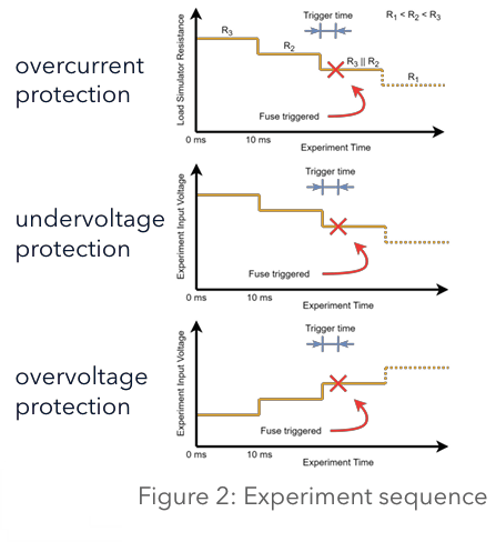
Demonstrate Over-Voltage Protection (OVP), Under-Voltage Protection (UVP), and Over-Current Protection (OCP).
-
Measure long-term performance under Total Ionizing Dose (TID) up to 50 krad.
-
Collect environmental data for future missions.
Tested Components
Three Devices Under Test (DUT):
-
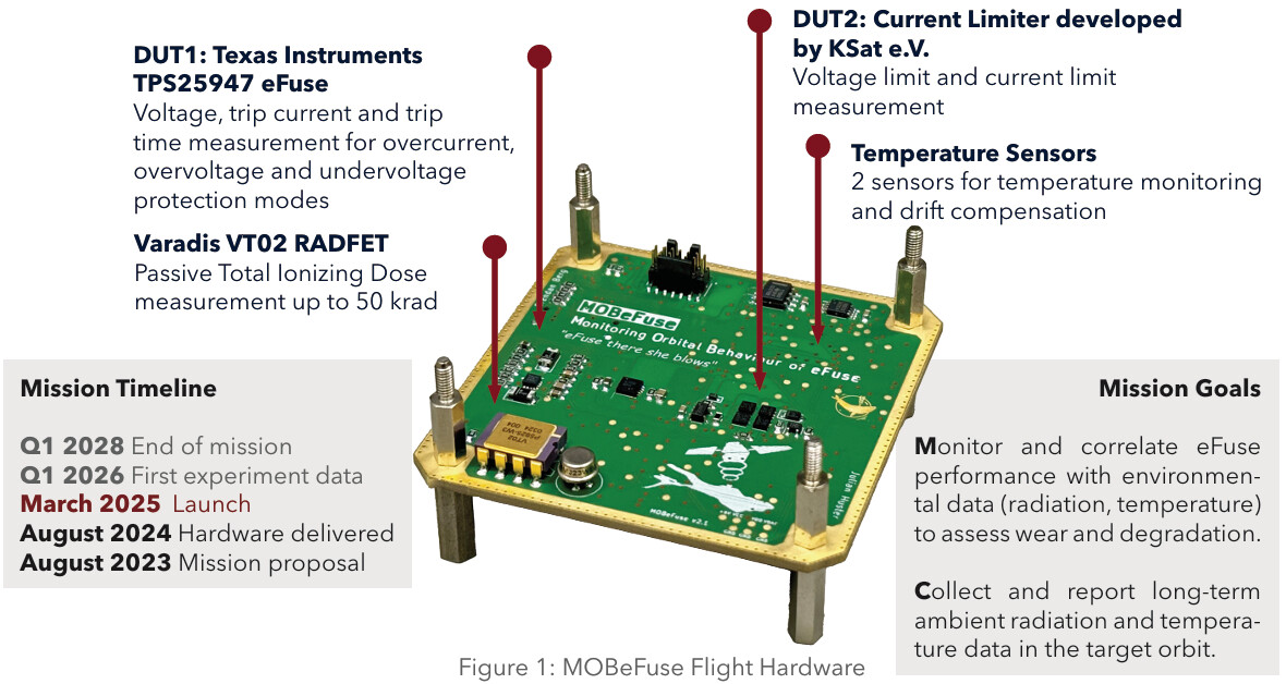
TPS25947 (Texas Instruments): Configurable thresholds, full shutdown on overcurrent.
-
NIS6150 (Onsemi): Fixed UVP/OVP, voltage reduction on overcurrent.
-
LCL (KSat e.V.): Reference design at TRL 6.
Additional: Varadis VT02 RADFET for TID, DS18B20 temperature sensors.
Technical Architecture
-
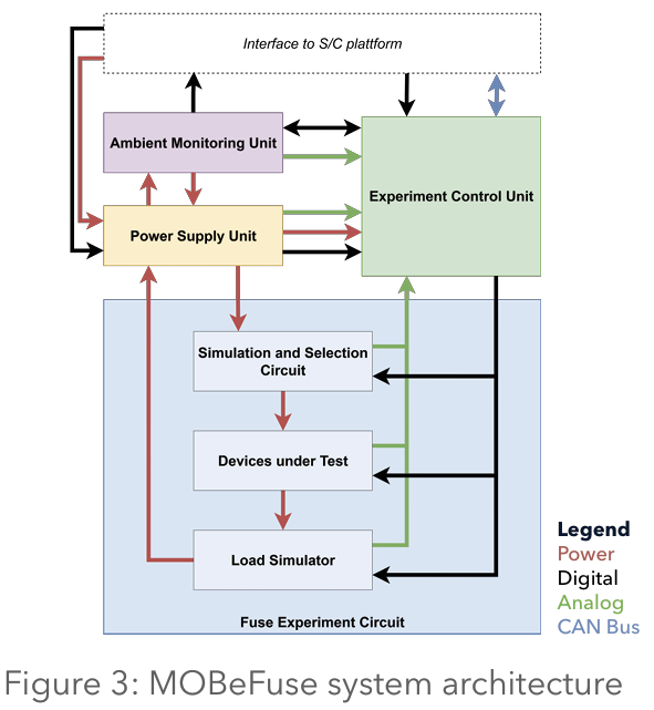
Power Supply Unit (PSU): Supports up to 8.6 V input.
-
Ambient Monitoring Unit (AMU): Records environmental parameters every 16 s.
-
Fuse Experiment Circuit (FEC): Simulates variable load and voltage conditions.
-
Experiment Control Unit (ECU): STM32G431 MCU with CAN/UAVCAN communication.
-
Test Cycles: 10 repetitions of OVP/UVP sweeps in 0.1 V steps and OCP tests at 3.3 V / 5 V. Each cycle lasts ~18 s.
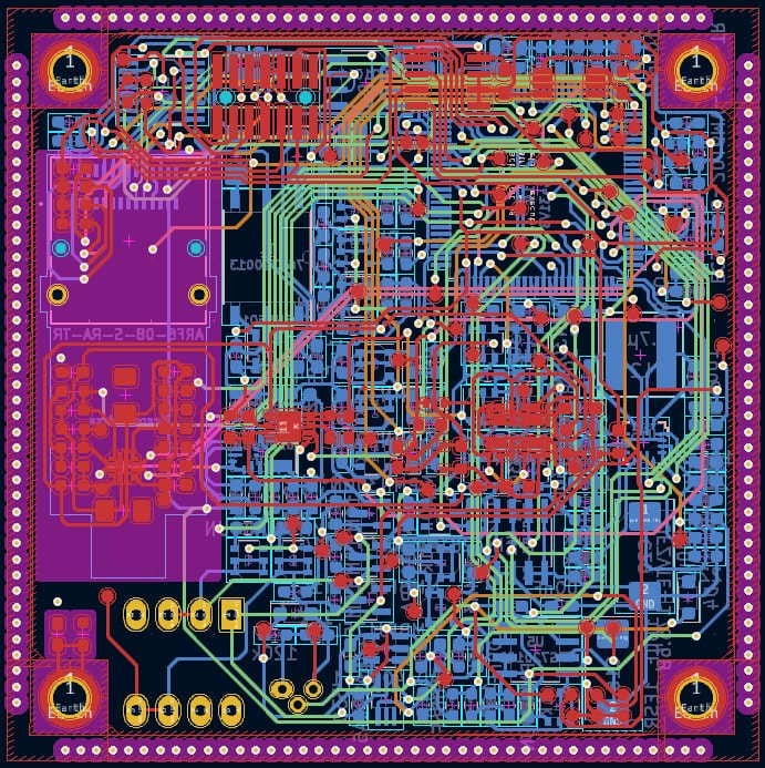
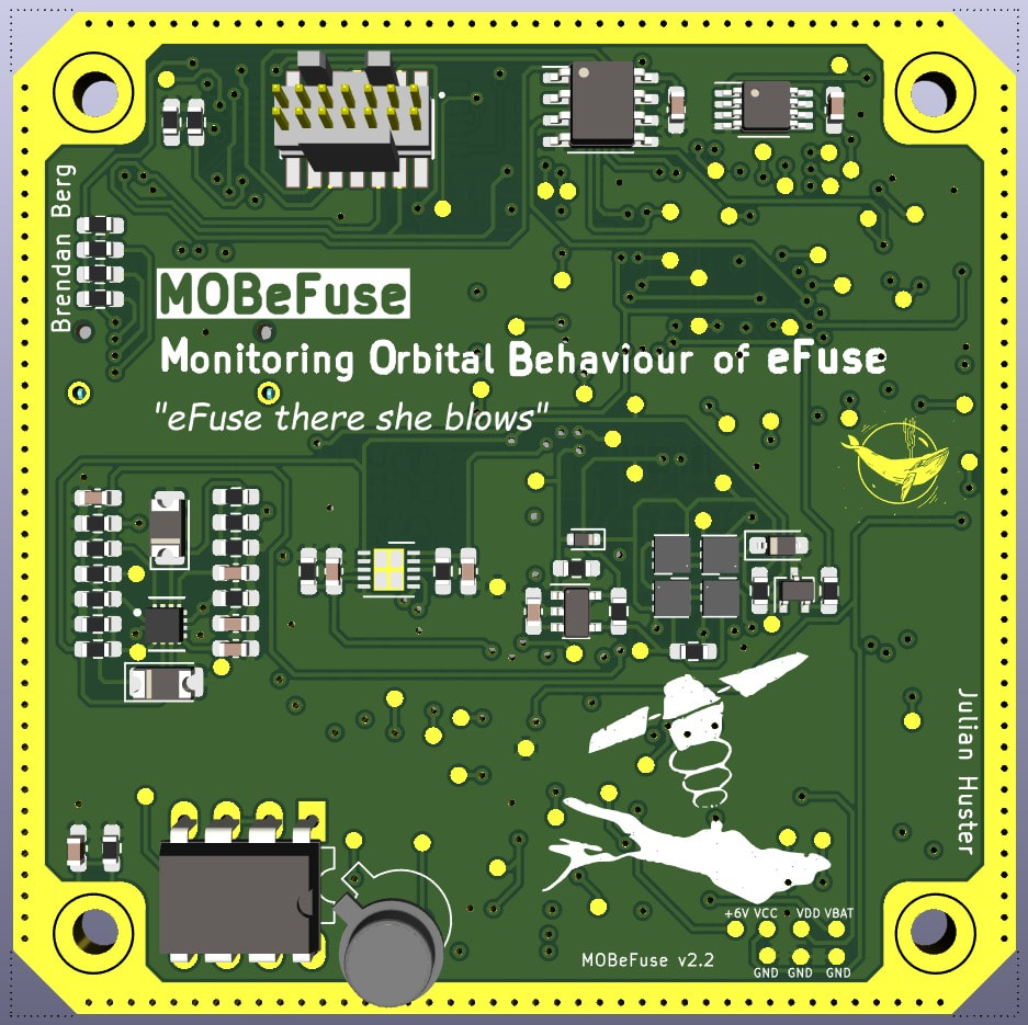
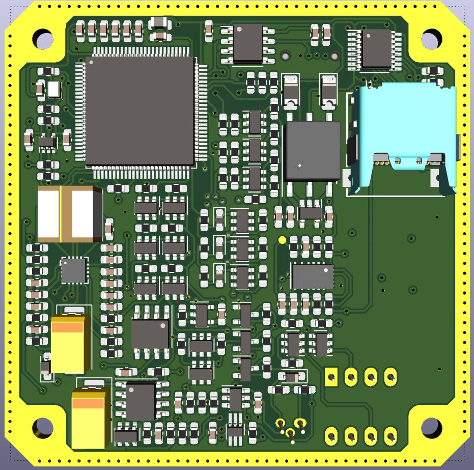
PCB Design
The MOBeFuse payload uses a compact 60 × 60 mm six-layer PCB integrating all power, sensing, and control functions. Around 250 components are mounted on the board, including eFuse ICs, sensors, amplifiers, and the STM32G431 microcontroller.
The board weighs 20.8 g with a height of 10 mm including all components and connectors. It was fully designed in KiCad, with 3D modeling for mechanical integration and pre‑flight verification.
We sincerely thank Aisler for their generous support in manufacturing and sponsoring the MOBeFuse boards, as well as for their technical assistance during the production process.
Timeline and Operations
-
August 2023: Mission proposal.
-
August 2024: Hardware delivery.
-
March 2025: Launch.
-
Q1 2026: First data.
-
Mission end Q1 2028.
Expected Results
MOBeFuse delivers essential data on the long-term reliability of COTS eFuses in operational environments. The results will refine the ERWIN CubeSat’s EPS design and provide reference data for future student, academic, and NewSpace missions.