Hey folks,
we are at it again, it’s Os.Car Racing Team, the Formula Student based at the University of Applied Sciences in Vienna. If you do not know what we do, our team builds a prototype ICE and hybrid-powered Formula Student car which we compete at various Formula Student competitions within Europe.
Os.Car Racing Team has been to three various competitions such as FS Czech, FS Austria and FS Alpe Adria this season. With our last competition completed we have achieved a huge milestone in the team’s history. This year’s car, called the CR-126h, also nicknamed as “Karli”, finished 2 out of 3 Endurance runs, which is the longest and harshest race format any Formula Student car can experience during each competition week.
In this article though, we will talk about the most important electronics needed for any driver, the Steering Wheel PCB.
What is the purpose of the Steering Wheel PCB?
The PCB is of high importance, as it is the sole input device between driver and the vehicle’s ECU, short for Engine Control Unit, during dynamic events. As any standard vehicle system nowadays the Steering Wheel Electronics relies on the onboards CAN-Bus communiation to transmit the Driver Inputs to the ECU. This is achieved through a configuration of 6 pushbuttons, shift pedals on the back of the steering wheel and an additional rotary encoder. It also has a connector to plug in a display for Driver Inputs information. The software logic is programmed on the main Microcontroller a STM32 from the F4 family.
What design changes to the Steering Wheel PCB have been made?
As every year we always try to find a way to minimize necessary PCB size and trace length with the goal in mind to reduce manufacturing time and cost. Furthermore on the economic topic, we have achieved BOM standardization for passive components such as capacitors and resistors, as well as, several components needed for the different power stages on the PCB as well as the transceiver needed for CAN-Bus communication. With that we are able to use the same component on any other PCBs we have developed this year.
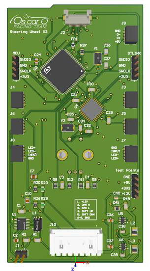
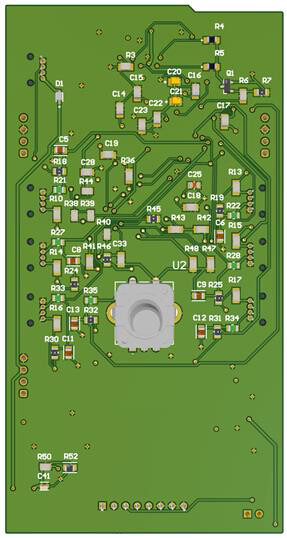
The biggest change is the introduction of Molex Micro Lock connectors used for connecting the pushbuttons for Driver Inputs to the PCB. In past iterations the connection was made through soldering which made maintainibility way harder, as basically the PCB was built in permanently into the Steering Wheel housing. With this problem resolved we can easily remove the PCB as well as pushbuttons and also have the option to rearrange the position of the buttons on the Steering Wheel to suit driver preferences.
The PCB itself is of 1.6mm thickness, made up of a 4 Layer ENIG surface finish, only possible thanks to AISLER manufacturing capabilities. With the Stellar Stencil we could easily assemble the PCB swiftly and with no stressful debugging due to human errors.
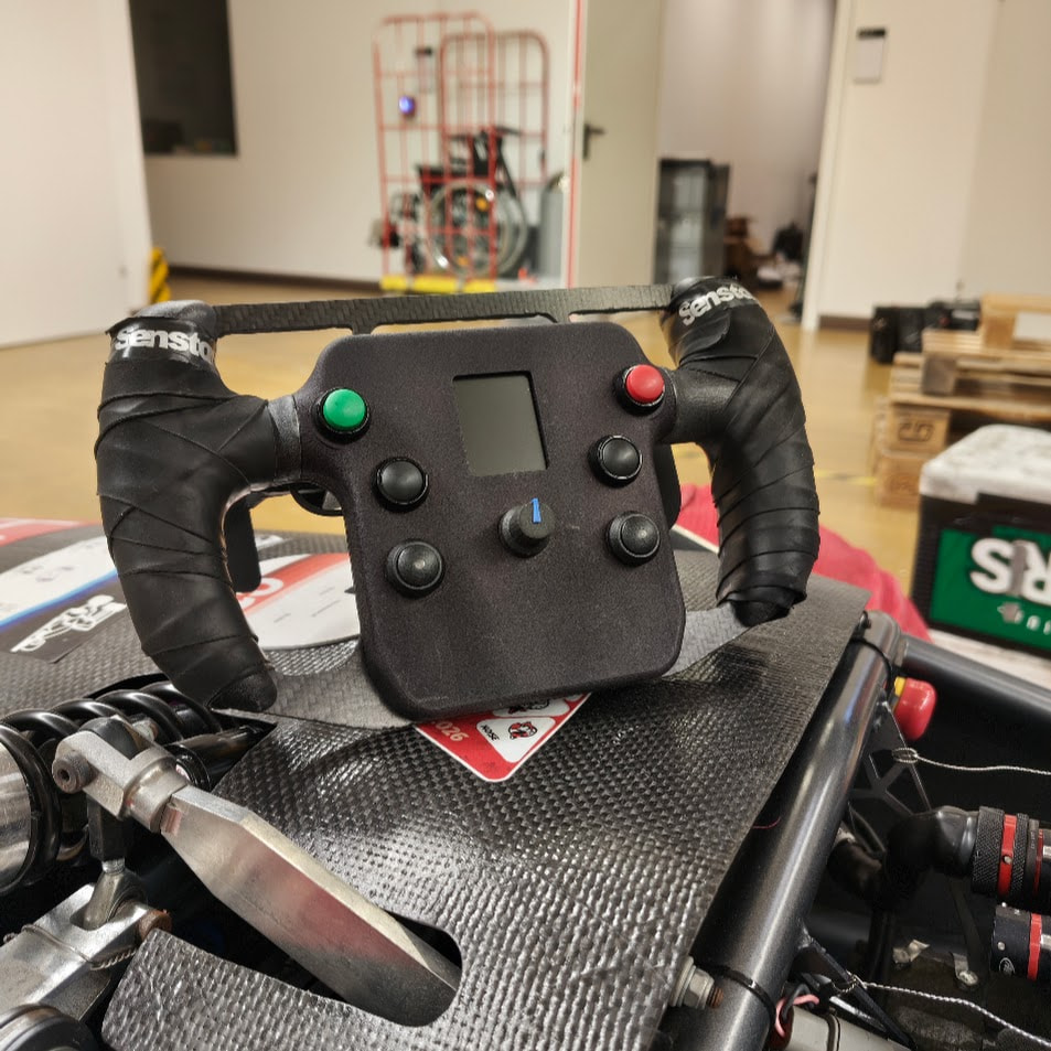
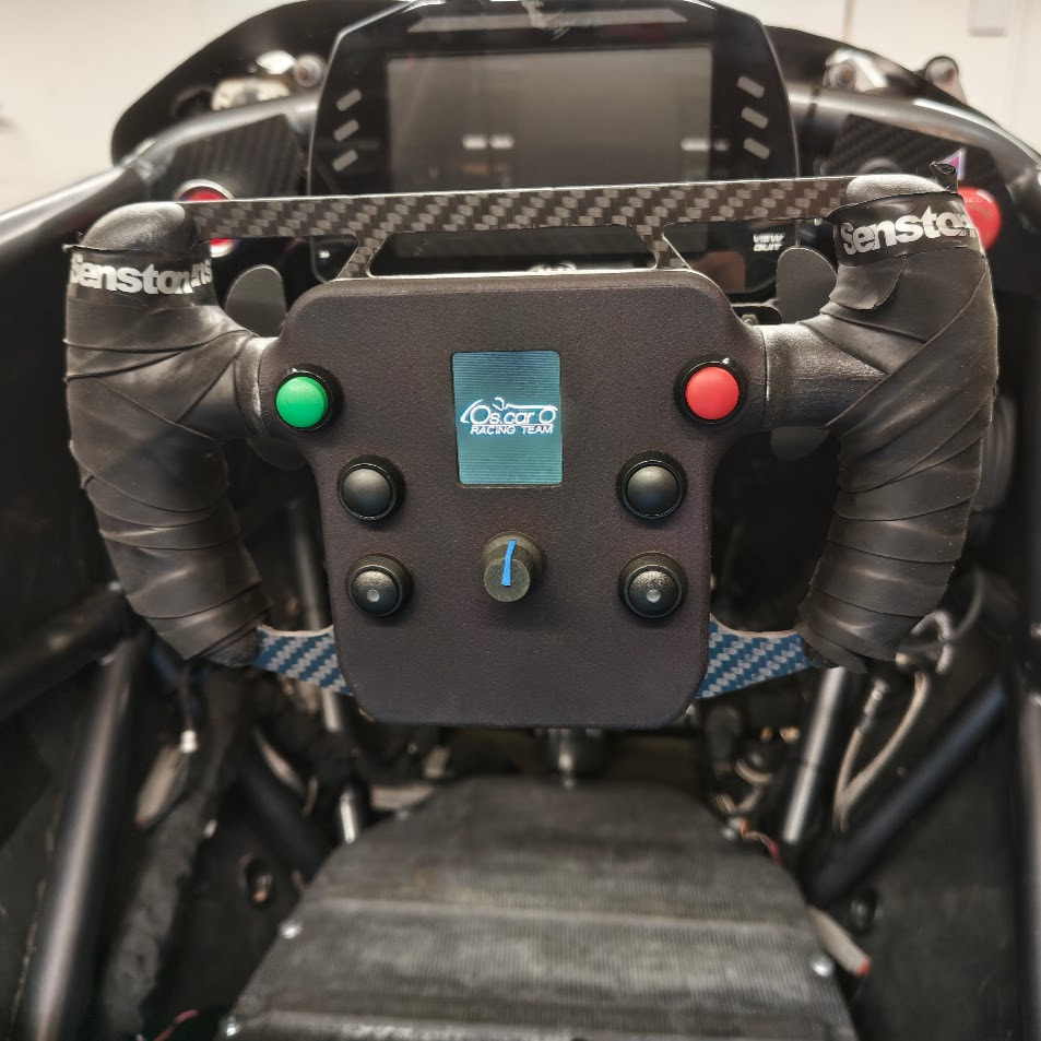
We cannot thank AISLER enough for their quick and easy PCB manufacturing service! Without their support to our project it would not have been possible to produce a variety of different core components for our Formula Student car.
Cheers, and see you next time!