Hi Aisler!
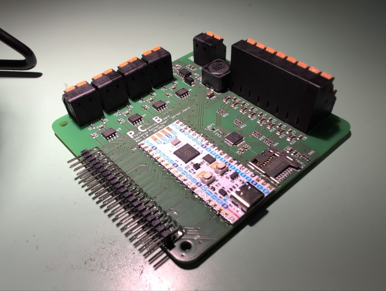
This is our attempt at a sensor reading board to handle all the data coming from our new experimental Hybrid Rocket Engine.
What is a Hybrid Rocket Engine?
Most commonly, when we look at a commercial rocket, we see liquid rocket engines. These engines burn a liquid fuel together with a liquid oxidizer, such as hydrogen or kerosene and oxygen. They are usually efficient, controllable, and powerful, but they are also extremely complex and expensive to design and build.
Another common type of rocket engine is the solid rocket motor (SRM). These engines carry a mixture of solid materials that, once ignited, burn in a controlled manner. Although they are generally less efficient than liquid engines, they are among the most powerful rocket engines available and are relatively inexpensive and simple to manufacture. However, they pose significant risks during both production and operation. Once ignited, a solid rocket motor cannot be shut down, making handling and flight operations potentially dangerous.
This leads us to hybrid rocket engines. Hybrid rockets typically use a solid fuel and a liquid oxidizer. In our case, the fuel consists of ABS and paraffin wax (similar to candle wax), while the oxidizer is nitrous oxide (commonly known as “laughing gas”). This combination makes the system significantly safer to handle, as the components cannot ignite on their own and will only react when brought together in the presence of a heat source. Additionally, the engine can be shut down at any time by stopping the oxidizer flow, allowing tests to be terminated safely if necessary.
The system also includes a nitrogen tank used as a pressurizing agent to maintain constant pressure in both the oxidizer tank and the combustion chamber.

Why did we build this board?
Building a Rocket Engine is not easy and definitely not cheap. For this reason we decided to create the necessary data logging equipment ourselves. Our objective is the logging of data from 4 different pressure transducers and 3 different thermocouples to observe and characterize the hybrid engine feeding system and the combustion chamber itself. This is then paired with the reading from a load cell, to obtain the true thrust of the engine.
This task must be accomplished with a high sampling frequency, to get the most data out of every test. This might seem daunting as sampling frequency depends on the phenomenon that we might want to observe but, fortunately for us, we are limited by the sensors themselves. In fact, taking the pressure transducer as an example, we can calculate the maximum bandwidth output by the sensor as a function of its rise time: BW = 0.35 / Tr. In our case we can check that the rise time of our pressure transducers is of 1 ms which mean that the signal has a maximum bandwidth of 350 Hz. To get a complete digital representation of the signal we can use the Nyquist Theorem, and get a sampling frequency of 700 Hz.
While still not being an easy task, it is still doable with a couple of precautions taken in the design. Nonetheless we tested the design up to 2 KHz, with good results, and expect it to reach even higher frequencies if pushed.
Micro Controller
Usually the choice of microcontroller is quite nuanced on the base of speed, features and costs. Yet, nowadays, all the most common microcontrollers bring to the table huge powers and a vast set of interfaces. Common names include the RP series from the Raspberry company, the lower classes of the ST family, most of the products of Espressif and some of the newer products of Atmega.
We decided to go along using the RP2350 in the form factor of the pi pico 2 for our familiarity with it. It would not be surprising if you could get the same result with any other modern microcontroller. This 5 euro board sports a 2 cores Arm-Cortex M33 running at 125 MHz (even if boostable to 200 MHz) with dual SPI and dual I2C interface.
While not being strictly necessary, the two core design let us separate between the sampling task and the recording task, allowing us to ensure that all the data is picked up at the right time, without discrepancy caused by the random behaviour of SD saving times.
ADC
We needed to read a signal from a pressure transducer, which outputs a current signal from 4 to 20 mA. This meant we needed to sense the current passing through the circuit. This can simply be done with a precision resistor. A filtering capacitor of 10 nF is added to reduce high frequency noise as suggested by the datasheet.
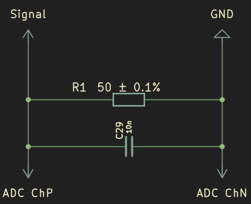
While not being experts on the matter, we went with a safe choice from Texas Instrument: a ADS131M08. This is a 8-channel sigma-delta 24 bit ADC. This has a range from -1 to 1 Volt, which means that the maximum precision we can get is 2 / 2^24 Volts or about 1.2 * 10^-7. We put all the channels in a current sense configuration, using a 50 +/- 0.1% resistance between the positive and negative signal terminal.
This ADC is made to run at 32 Ksps (Kilo Sample Per Second) but we don’t need such a high sampling rate, so we reduce the speed in the setting and we poll the data from the mcu at the maximum frequency possible to avoid data loss.
Thermocouples
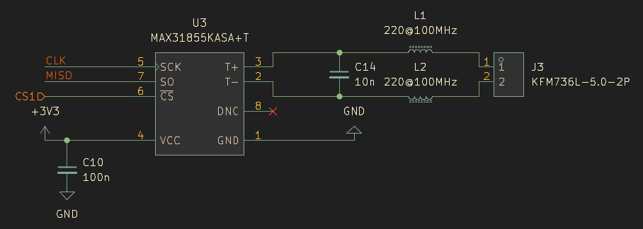
We opted for the MAX31855K as a complete solution for reading K type thermocouples. These are very easy chips that spit out on the SPI channel any reading they have every fifth of a second. We just implemented the analog frontend exactly as cited in the datasheet. This helps filter out any Radio Frequency caught by long probes that could alter the reading. As usual a decoupling capacitor on the power supply helps stabilize the power line on the chip.
Connectors
We wanted to use this opportunity to explore new alternatives for connectors that were spring locked, and not fixed by screws. We found these Cixi Kefa Elec KFM family of connectors, and tried them out. While we expected a Wago-like experience, it didn’t totally turn out that way. The spring system is depressed with a slot that can be actuated only by a flat-head screwdriver, defeating the purpose of the choice. They are still good quality connectors, with a very good grip and a strong plastic casing, but we noticed quick deterioration of the switch head if not used cautiously.
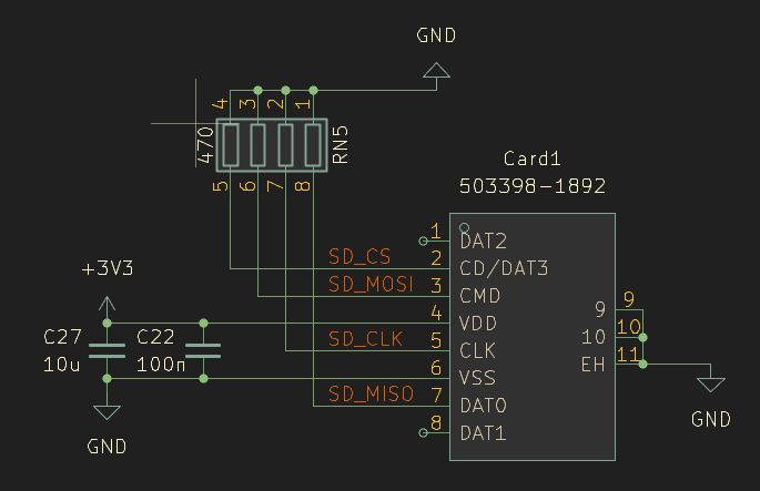
SD Card
Data logging is always a big deal in amateur systems. While being quite easy on the connections side, it represents the only true high-speed connection on the board running at around 31 MHz. Usually it is connected through a SDIO channel, which can be emulated with one of the PIO cores of the RP2350, but for the sake of not using too many pins we decided to use a simple SPI connection. The only concern to maintain is the pull-downs on the data lines, which greatly improve the signal integrity on this channel.
As for the saved data, we save everything in a clear text CSV file. This is not optimal, as the amount of data moved on the SPI channel and the dimension of the files are way larger than they should be. We figured that the channel had enough bandwidth to support this save format anyway, so we chose to have a easier time handling the files rather than an efficient system. While this could be a bottle neck if we ever need to achieve higher speeds, the change that needs to be made is purely software and does not prospect an enormous amount of development time.
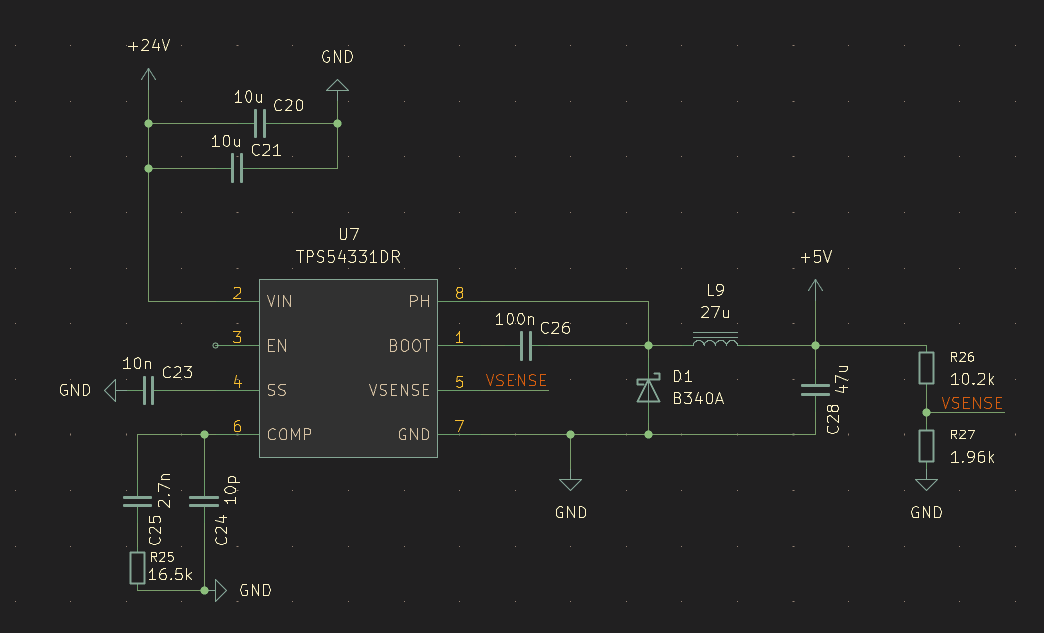
Power Supply
As before we wanted to experiment. Our requirement was for a power supply that could handle the 3.3V supply needed for the logic circuitry from any source up to 24V. So we decided to try out the TPS54331DR from Texas Instrument, a 570 KHz switching step-down converter that handles up to 28 Volts. We copied the relevant schematic from the datasheet and had no problem whatsoever. Our only remark is the choice of inductor used, that ended up taking a bit too much space on the PCB.
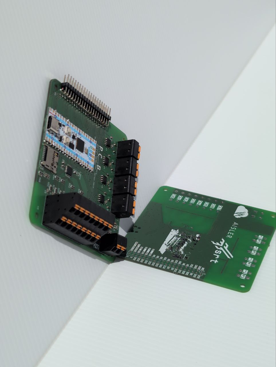
Final Result
We are content with the final result! The board has proven to be reliable during our initial tests, providing clean data that is vital for our engine development. It proves that you don’t need an unlimited budget to perform “rocket science”—just some patience, the right components, and a solid PCB design. We hope this breakdown inspires others in the Aisler community to tackle their own high-speed data logging projects. If you have any questions about the schematics or the code, feel free to ask in the comments!