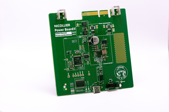
As the name suggests, the power board deals with every power-related tasks within the system. It has three main functionalities, namely supplying power to the system, switching between different power supplies and monitoring of power consumption. The main battery pack is a 6S Li-ion pack that is connected directly to the power board. The power board also communicates with the flight computer board through CAN Bus.
The avionics system of the rocket requires 3 different voltage supplies, namely VBAT (~24V), 5V and 3.3V. The VBAT and 5V rails are distributed from the power board to the rest of the stack and the 3.3V is supplied by converting 5V to 3.3V with an LDO that is located on each board. VBAT is the voltage supplied by the supply, which would have the nominal value of 24V. The 5V rail is supplied by the power board by converting VBAT to 5V using the LT8648S, a buck converter manufactured by Analog Devices. All voltage rails that are supplied by the power board are transmitted through the backplane that connects all the main boards of the system.
The power board also enables automatic power supply switching between the external power supply and the internal battery pack. The rocket needs an external power supply before the launch, mainly to preserve battery life during assembly and pre-launch checks, which requires smooth switching. This was enabled by an ideal diode IC, namely the LTC4416 from Analog Devices. With this, once an external power supply is connected to the stack, the power supplied to the whole stack is no longer supplied by the battery pack, but the external power. Once external power is disconnected, power supply changes back to battery pack without interruption.
The power board is equipped with 2 current sensors in order to track power consumption of the system. The two current sensors monitor the VBAT and 5V power rails by measuring the voltage and current going through the shunt resistor connected to each sensor. The current sensor used is the LTC2945 by Analog Devices. These current sensors are connected through the I2C protocol with the MCU. The MCU will then communicate with the flight computer through CAN Bus, as previously mentioned. For on-board logging of the power measurements an external flash chip is also present on the board.
