Introduction
Honored browser of the Interweb,
Greetings from Team Solaride, a student solar car team from Estonia. We’re building our (and indeed the Baltic’s) fourth solar-powered car, competing in the Cruiser Class. As with every season, this season brings a brand new car, 70-ish happy members and a goal to finish first in our class in the 2027 Bridgestone World Solar Challenge held in Australia.
Radio / Intercom board
The what and why
In this post we’d like to showcase our initial design for our communications PCB. This board came to be as a result of three issues:
- The inside of our car is fairly loud, which makes communication between the driver and copilot rather difficult;
- A good chunk of the radio communications coming from the car are, to put it mildly, somewhat unintelligible;
- Ideally we’d like to extend our radio communications to the web, so that our team members further away from the main convoy can still be in touch with the rest. In addition, the media team will be more than happy for some race comms audio - win-win!
The plan
As with any great engineering project, everything starts with a plan (which inevitably will go wrong). I started off with a plan of what the board must (eventually) do:
- 2x mic and headphone interfaces for the driver and copilot. The communication between occupants should be based on Voice Activity Detection, meaning they shouldn’t have to press anything to talk;
- A way to interface with a standard handheld radio + a way to trigger the Push-To-Talk on it;
- A way to make the board interface with a computer, so that it could be used as an audio device, essentially creating a VoIP radio.
My initial thought was to proceed with normal 3.5 mm headphones (which no-one apparently has anymore), as they’re the most accessible mic+headphones combo with a well-known connector+pinout (plus they’re cheap). The interface for the radio took some figuring out, as every manufacturer seems to have a slightly different pinout and PTT connection logic, but after an afternoon with an oscilloscope I got the pinout and voltages figured out.
The design
I chose a 4-layer PCB (two internal GNDs) for this project due to the number of sensitive audio signals and number of data buses. The board was designed in Altium.
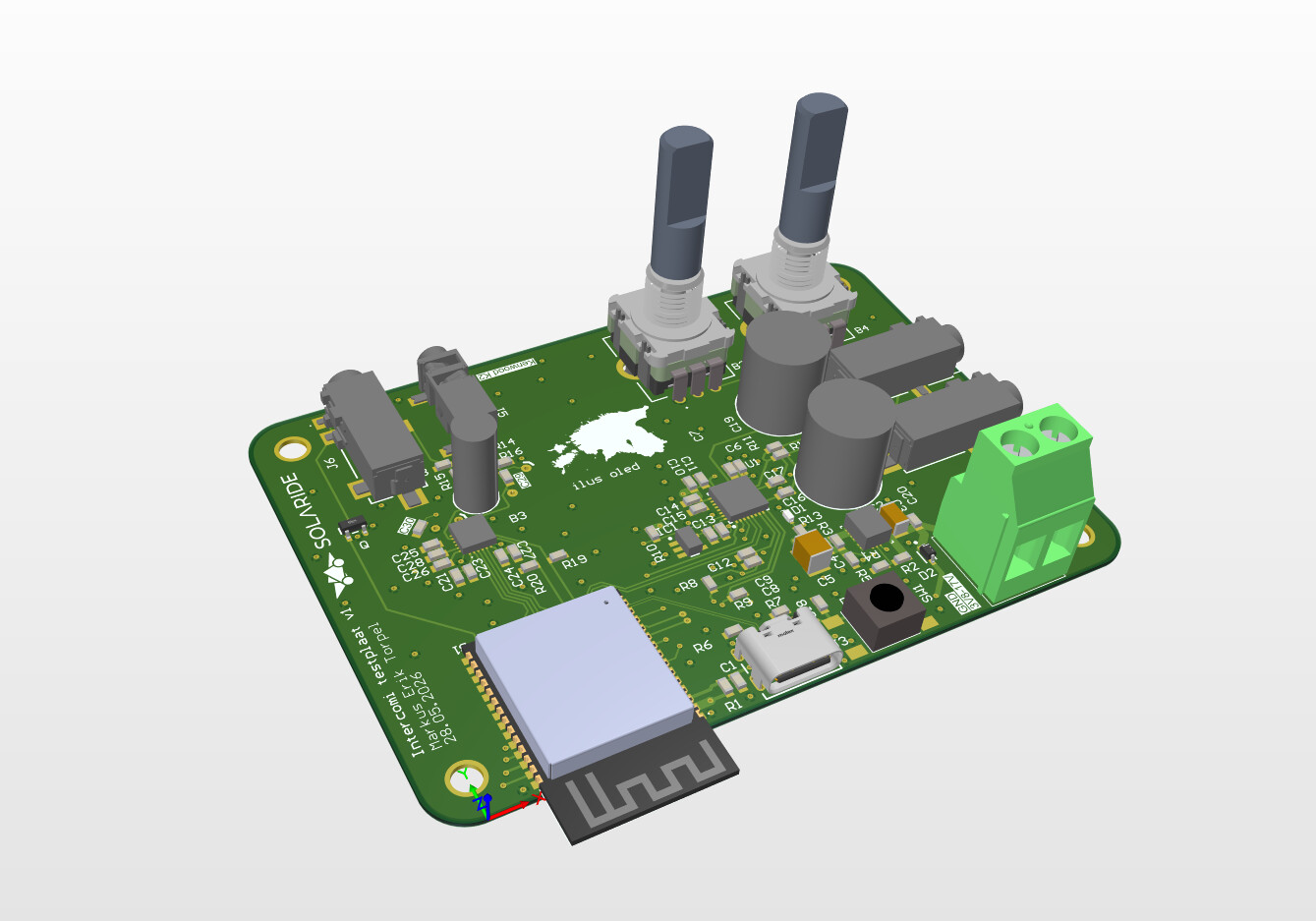
The board features an ESP32-S3 SoC and two audio codecs. The microcontroller transfers and processes digitized audio moving between the two occupants as well as the radio. The audio codecs have built in ADCs and DACs, making them the bridges between digital audio and the real analogue world. As the radio outputs a voltage to drive a speaker/headphones, a simple voltage divider was calculated to reduce the input voltage to an acceptable range for the audio codec.
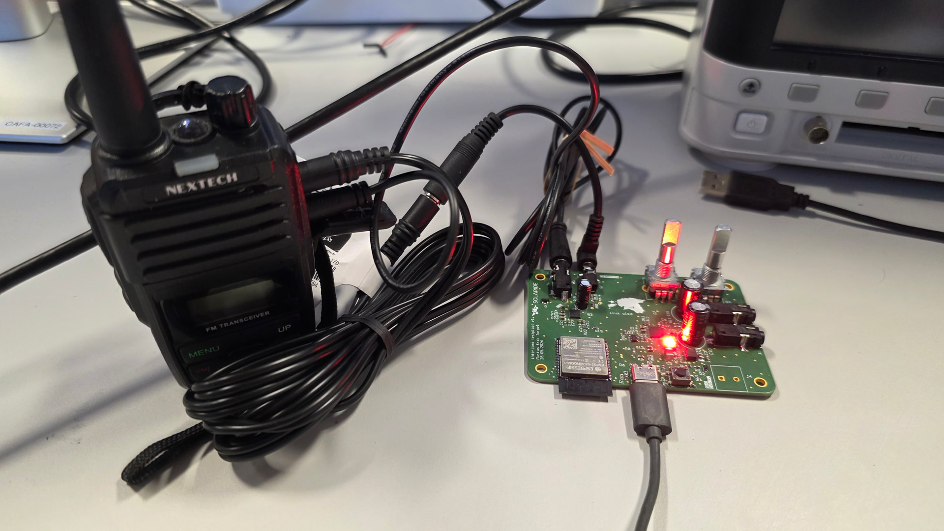
Here are some photos of the actual board (this is revision 2). As you can see, the resistor for the LED isn’t quite big enough (and this pcb will literally blind you if you look at it).
Achievements and lessons learnt
- It actually works (50% of it at least)! I can connect the board to my computer and use my radio through any app (e.g. Discord);
- Audio signals require proper capacitors (and other components), as some will have a voltage-dependent capacitance which will ruin your audio;
- The audio outputs are fairly finicky and I managed to burn down an amplifier on one of the codecs. As a result, I could really only work on the radio interface part.
- Properly reading datasheets beforehand will save you lots of trouble and time further down the line.
Final thoughts
I’ll post some updates once I get the next iteration going. I’ll be moving away from the 3.5 mm headphones in favor of proper noise-cancelling electret microphones.
Finally, we are eternally grateful to Aisler for their continued support and sponsorship. Your support is helping to shape and inspire the next generation of young engineers! We couldn’t be more pleased with the speed of iteration and quality (as well as that the boards are made in Europe).
Hope to see some of you in Australia!
Team Solaride