FENRIR is a student experiment based at Luleå University of Technology, which will fly on board of cycle 15 REXUS34 rocket in 2025. The experiment belongs to the Deployment Systems category, and the main focus is the development of an easy-to-use platform for future free-falling experiments that need to be ejected from sounding rockets. The major goal of this platform is to eject a payload housing Free Falling Unit from a Rocket Mounted Unit and safely recover it with the help of a parachute. To prove the feasibility of the platform, two payloads will be housed within the FFU: an Attitude Stabilisation System (ATSS) and an experiment in the field of Phase Change Material (PCM) Science.
The ATSS, which is in part a legacy of the RX30 project Attitude Stabilized Free Falling Experiment (ASTER), will stabilize the FFU and therefore enhance the reduced gravity conditions for other experiments housed within the platform. The second payload observes the behaviour of PCMs in a reduced gravity environment. This class of materials is of particular interest since they can offer an order of magnitude increase in heat capacity with very small or negligible temperature change, compared to other commonly used materials in space applications.
The platform is designed to be modular, offering future students the opportunity to include their own scientific experiments as seen fit, thus lowering the threshold for reduced gravity research.
For this purpose, we’ve designed five boards, three of which are part of our platform, and two of which are part of our payloads inside the FFU.
The modular system consists of:
- RMU PCB - This board is the electrical interface between our experiment and the rocket’s electronics. It downregulates voltages and converts received signals from RS-422 to UART. These signals are then routed to our EPS PCB. This PCB also houses a camera, which will record the ejection of our FFU from inside the rocket.
- EPS PCB - This is the power board which regulates voltages and prevents our Li-Ion batteries from catching on fire. It produces three voltages: +3.3V, +5V, and +12V. Out of these, the Main PCB computer only uses the +3.3V line, whilst the other two are for housed payloads. This board also forwards signals between the RMU PCB and the Main PCB.
- Main PCB - This is the brains of our FFU. It controls payloads, records the descent (using an outward facing camera), and most importantly handles the recovery of the FFU. It does this by estimating the altitude from a pressure reading, and from this deploys a parachute when we reach the desired height. Crucially, it also receives its position using GNSS and transmits this position to the Iridium constellation, who provides us with the data to our ground station.
The two payloads consists of:
- ATSS PCB - This is the link between our Main board and our reaction wheels. It houses three motor controllers which each control their own motor and attached reaction wheel. These reaction wheels will slow down the rotation of the FFU during free fall, and by doing this, potentially increase the quality of the microgravity. This board also houses big capacitors and an overvoltage protection circuit which stores energy and disconnects the power coming from the Main PCB when the voltage rises due to braking of the wheels. This improves the efficiency of the payload, as it can reuse some of the energy otherwise lost during braking.
- PCM PCB - This is the scientific experiment of our project. It houses our phase change material (PCM) in a container. The board will heat up and measure the temperature gradient of our PCM using a heater and four temperature sensors. Specifically, we are aiming for it to undergo a phase change during the free fall, and to study the effect of microgravity on such a transition. The board also houses a camera and supporting LEDs, which will record and illuminate the PCM during descent.
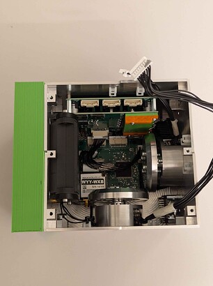
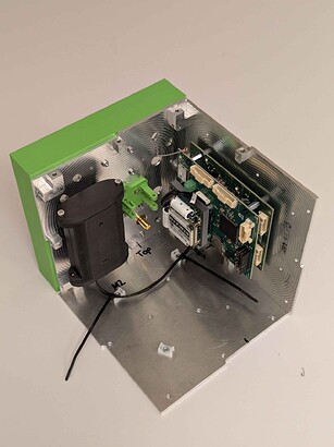
Below, you can see parts of our FFU during one of our many integrations.
In the first image, you can see our reaction wheels on the right and bottom, our battery compartment on the left, and our payload PCB stack at the top. Down in the centre is our EPS - Main PCB stack. In the second image, you can see our battery compartment and our EPS - Main PCB stack. The green box on the side of the FFU is our parachute compartment where we also house our GNSS receiver and Iridium transmitter.
(Some parts here are 3D printed replicas of our current parts)
We are currently in the later manufacturing & testing phase of our experiments lifecycle. This stage involves a lot of integrated testing, producing and evaluating procedures, and documenting our results. This phase started back in June and will end in mid December. Because of this high pace schedule to manufacture, test, and validate our experiment, we’ve also required our manufacturers to match this pace. This is where Aisler has been and continues to be a cornerstone of our success, as they not only supply us with high quality boards, but also generously support our project by giving us their service for free. So from the bottom of our hearts,
Thank you Aisler!

