Hello Aisler Community!
We are Sapienza Technology Team, a branch of SASA (Sapienza Aerospace Student Association) from University of Roma la Sapienza.
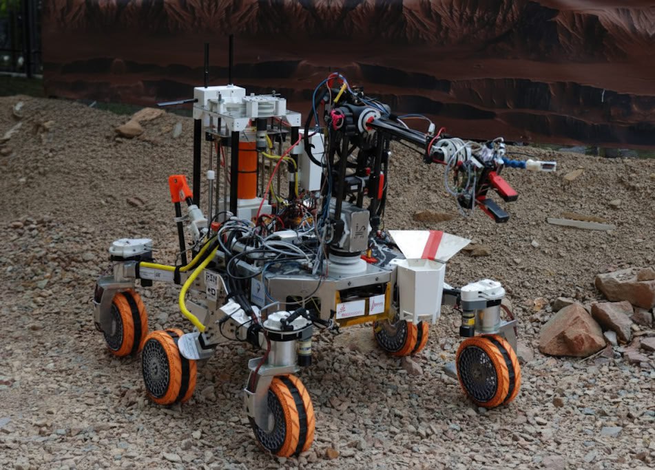
Our team’s objective is to design rover prototypes capable of autonomous navigation, sample analysis and maintenance operations using our 6-DOF robotic Arm and sampling modules. We have been participating to the European Rover Challenge for 4 years, and each year that passes we are pushed to improve our designs to keep up with all the other competitors. In order to do that, we are often forced to think outside of the box for most of our systems, and this year was no exception. Today we’ll show you how we’ve managed to get additional features on our stepper motor-based robotic arm, reducing cable clutter and using wireless communication within the system itself.
While the movement of the various joints is assigned to a simple yet effective ESP32-S3 breakout board located at the base of the robotic arm, we’ve decided to push our technical limits by developing a separate board mounted on the end effector itself. This has allowed us to implement more sensors and actuate the end effector separately, all while reducing the cable clutter coming from the base.
Arm Control - End Effector Board
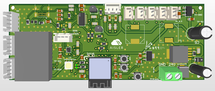
This was our first experience developing a complex, custom ESP32 board, but thanks to the team’s effort and with the help of AISLER’s technical support we’ve managed to get a working board within just a couple of renditions. We ended up with this 4 layers ENIG board, and here are some of the features and technical informations:
ESP32-S3-MINI-1
We chose this microcontroller module as the heart of this board for it’s dimensions, ease of use and power. Using the ESP-Now protocol, we were able to send all the collected data to the main board wirelessly, connecting the two boards via their hardware MAC and thus avoiding interferences from other wifi-based signals.
Power section
The board is powered by the 24V main line used for the stepper motors, properly stepped down and regulated via buck converters and separate linear regulators for the digital and analog portions of the circuit, as you can see on the right section of the board. The power connections are the only ones shared with the rest of the Arm module.
Upload section
On the top-left side, you’ll be able to see a UART bridge, namely the FT231XS. We could have used the ESP32’s native USB controller, but in order to facilitate board tests by our software division and for ease of use, we’ve decided to opt for this easier, arduino-like solution. for that same reason we’ve included a USB-C connector directly on the board.
Sensors section
Absolute Hall-effect encoders(AS5600) have been used to get precise readings of the actual position of the joints of the upper section of the robotic arm. These cheap i2c sensors are however limited by the fact that they have a fixed address, so in order to manage three of them we were forced to add an i2c multiplexer. The board also uses pressure sensors for the end effector’s fingertips, along with an IMU chip to get additional informations about the behaviour of the end effector during movements.