Hello fellow makers,
We are proud to share the second revision of our custom-built telemetry system.
The system is based on a Raspberry Pi Compute Module 5 (CM5), which serves as the heart of our car’s data infrastructure. It monitors all CAN buses in the vehicle, provides internet connectivity through a self-designed LTE module carrier, and enables over-the-air updates for all STM32-based microcontroller systems in the car.
The Telemetry is a life improving system for us. It allows us to access all vehicle data in real time, which enables faster and more precise setup validation during competitions and helps streamline testing sessions.
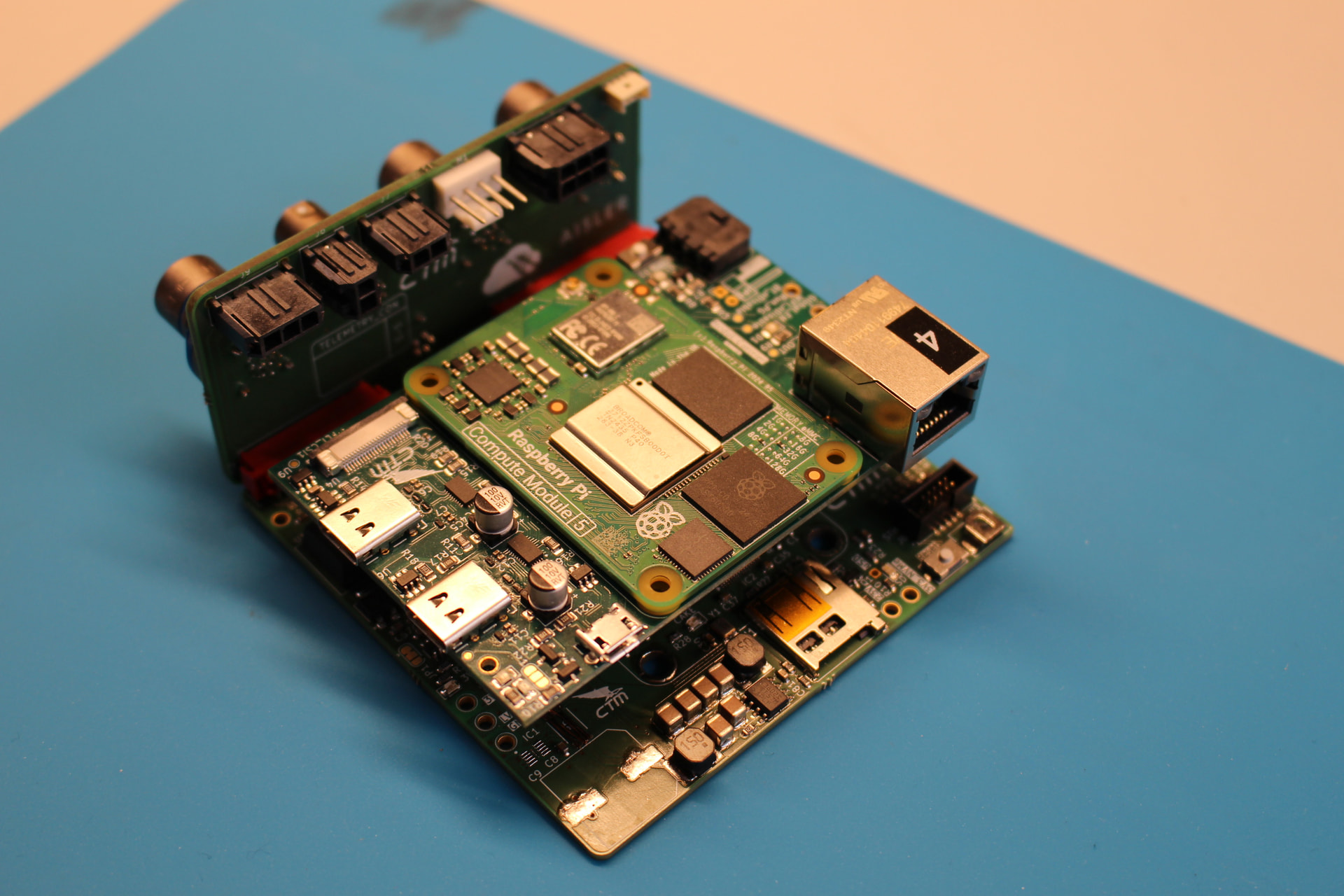
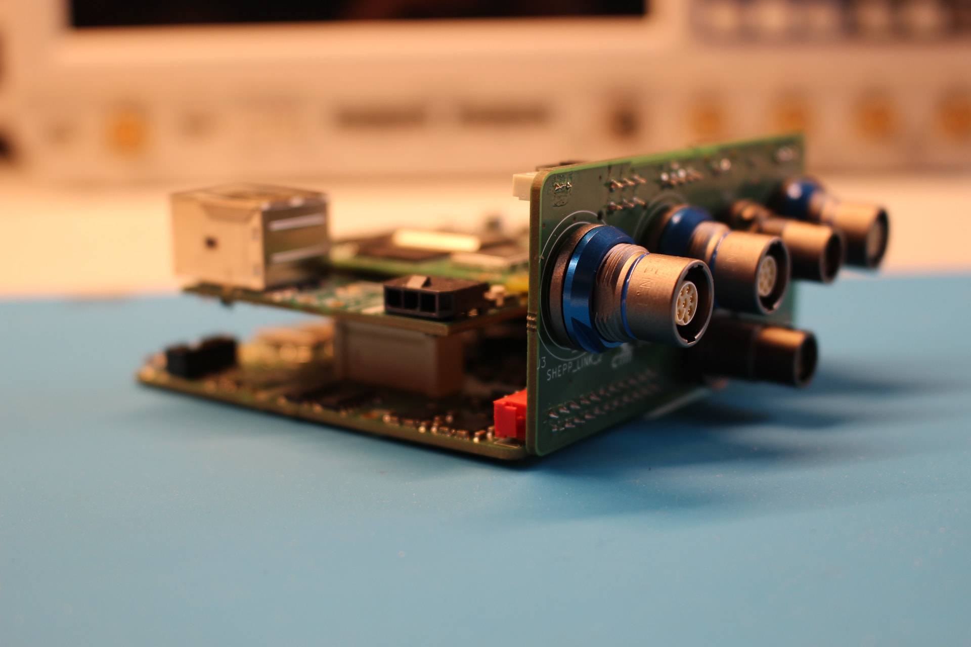
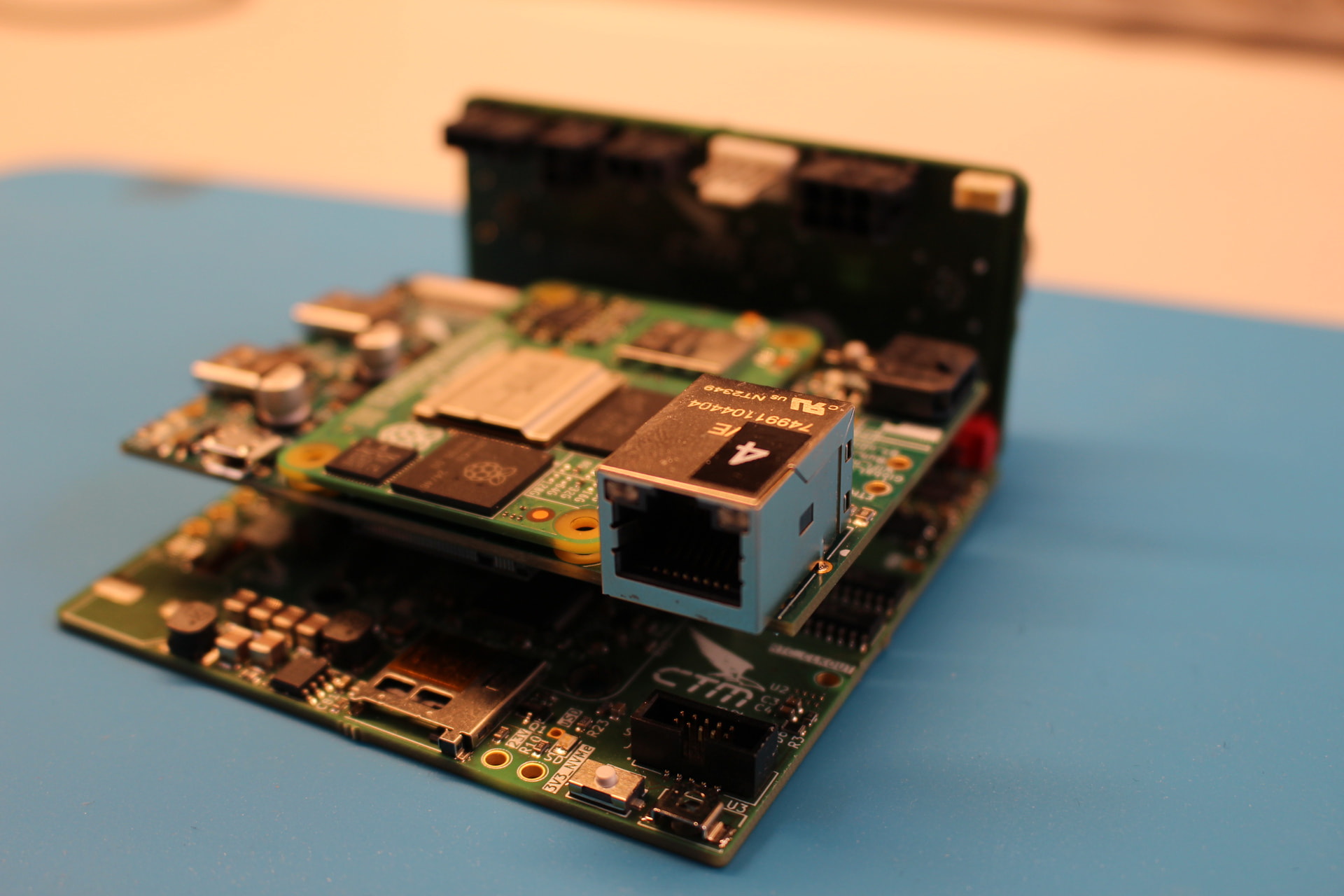
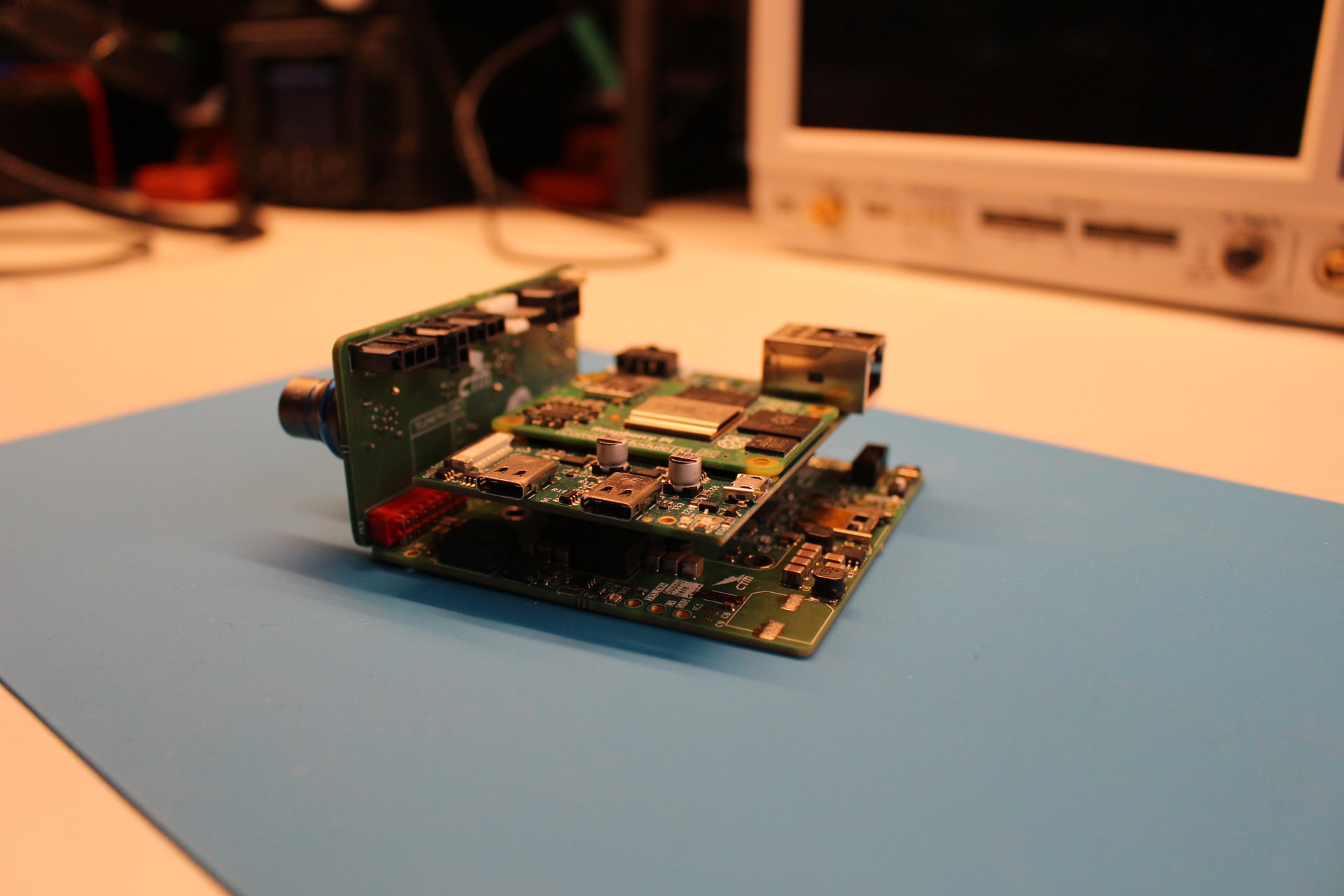
The system consists of three stacked PCBs and one connector board.
At the foundation is the Main Board, which hosts the STM32-based vehicle control unit as well as four CAN FD transceivers for the main CAN bus, the sensor CAN bus, the accumulator CAN bus, and the inverter CAN bus. These four CAN FD buses carry nearly all data generated throughout the car. The Main Board also generates all required supply voltages for both the CM5 and the LTE module.
Through a board-to-board connection, the Main Board is linked to the Carrier Board, on which the CM5 is mounted directly. This board handles all high-speed interfaces, including two USB-C 3.1 ports for the LTE module, two CSI interfaces for a camera mounted on the main hoop, an Ethernet port for communication with the car in case the LTE module cannot establish an internet connection, and a PCIe interface for an M.2 SSD.
During test sessions, all CAN bus data as well as the camera feed are stored locally on the SSD before being uploaded to our cloud infrastructure. This setup allows us to correlate vehicle data directly with video footage, giving us much deeper insight into how the car responds to driver inputs and behaves on track.
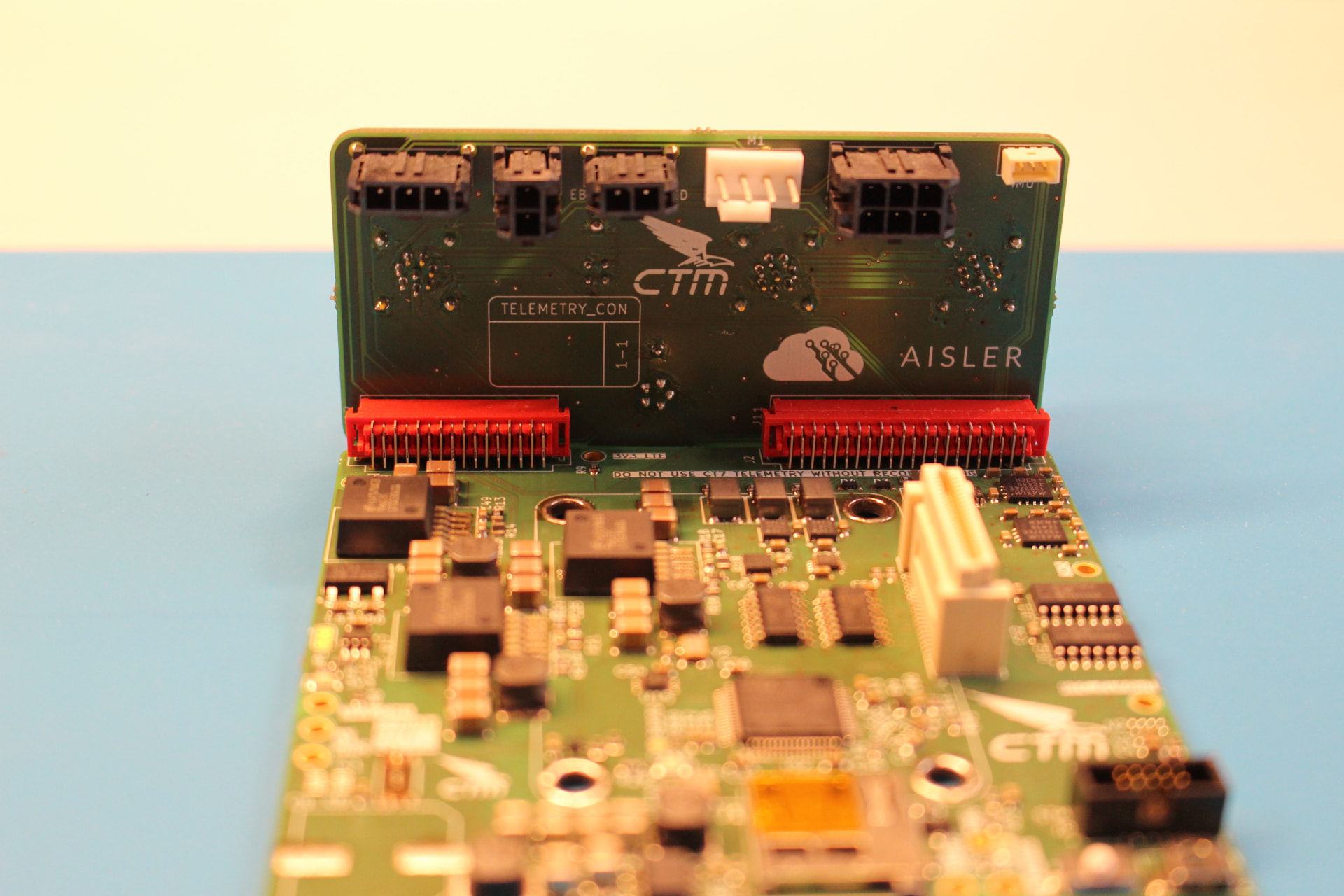
Also connected to the Main Board via board-to-board connectors is the Connector Board. This board is mounted directly to the outer panel of the telemetry enclosure, enabling a clean and service-friendly integration without cable clutter inside the housing.
The Connector Board carries keyed connectors for the car’s major subsystems, including the Accumulator Management System inside the accumulator, the inverter interface for our second generation of self-developed SiC inverters, and the front and rear SHEEP units — our modular sensor and actuator system, also developed in-house. We are looking forward to sharing more about these systems in future blog posts.
AISLER has been our main PCB supplier since 2021. Their excellent online Gerber viewer and support for KiCad board files make ordering PCBs quick and straightforward. The high quality of the boards, together with fast manufacturing and short delivery times, greatly supports our development cycle of designing, testing, and iterating.
And when mistakes happen — as they always do in hardware development — AISLER’s revisioning tool has proven especially valuable. It allows us to quickly order updated board versions and continue development without unnecessary delays.
We are very glad to have AISLER as a long-term sponsor, and we want to thank the entire AISLER team for their support over the past few years. Together, we have achieved our first podium results in international Formula Student competitions, and we hope many more will follow.
If you would like to learn more about us, we are Campus Tirol Motorsport, the Formula Student Team from Innsbruck. You can read more about Formula Student on the official Formula Student Germany website, and more about our team on our homepage.
Thank you for your support, and stay tuned for more insights into our electronics systems.