Hi everyone,
We are TU/ecomotive, a student team based at the Eindhoven University of Technology. Every year, we develop a new concept around the future of sustainable mobility. Our project this year does not have a final name yet, but it focuses on reducing particulate matter in the air by integrating our own semi-ENS system into the car, together with wheel caps that work on the same principle.
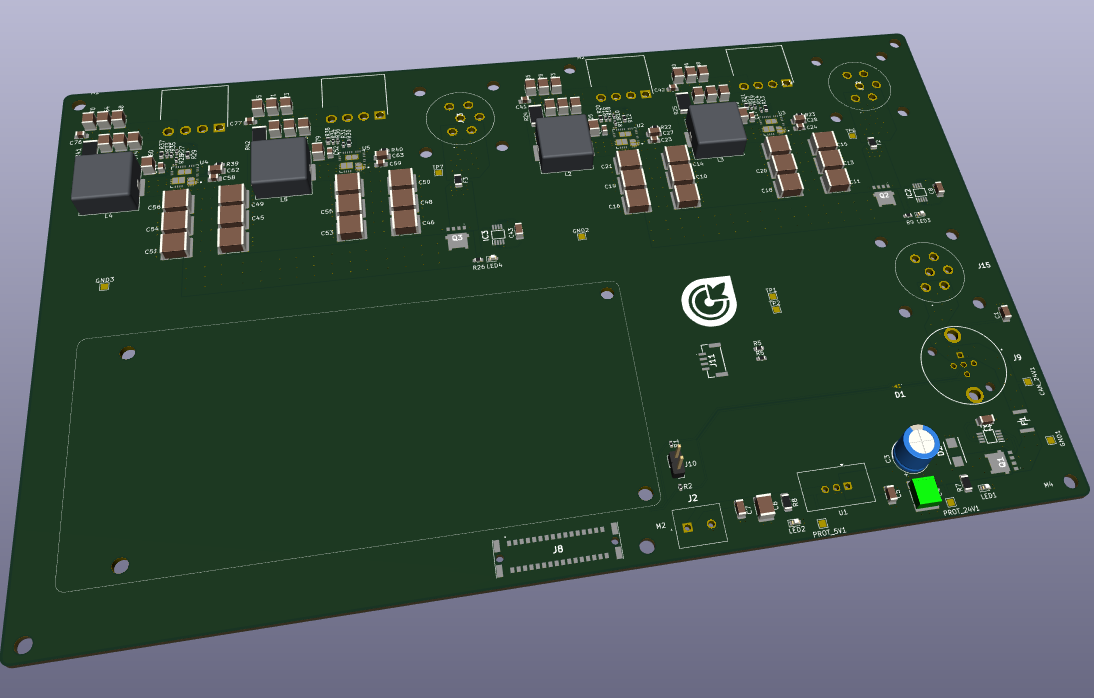
Within the team, we are part of the embedded systems department. We are responsible for several low-voltage systems in the car, including throttle-related electronics, power distribution, information systems, and lighting. One of the key PCBs we developed for this architecture is our Backbone PCB.
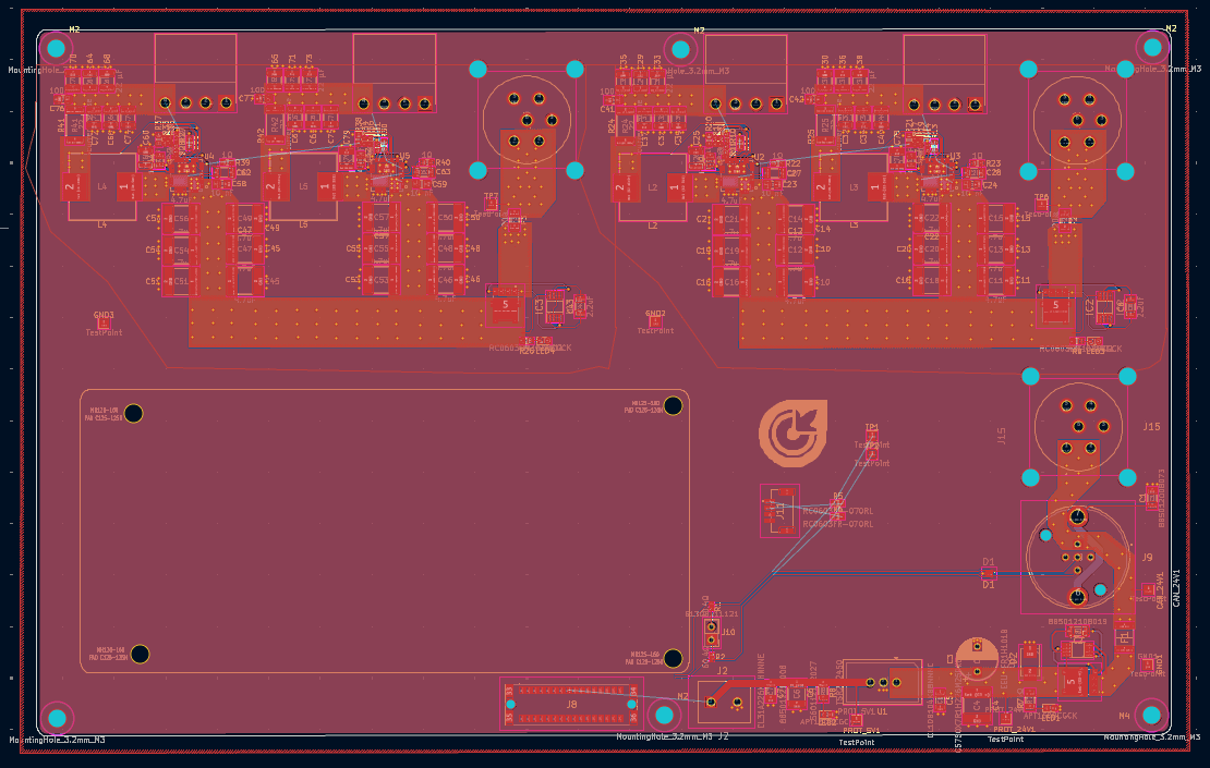
The Backbone PCB is designed as a central power and communication node. It converts the vehicle’s 24 V supply to 12 V and 8.4 V for other nodes in the system, which are used for loads such as LEDs and motors. In addition, the board also includes a 24 V to 5 V conversion for the microcontroller side of the system. The design is implemented on a 4-layer PCB.
A key feature of this board is that it is built per side, so the converter stage is effectively duplicated. This makes it easier for us to organize the system architecture and distribute power where needed. The board also routes CAN communication to the NXP microcontroller platform, and through the same connector we can also provide dedicated power to the FRDM NXP board.
One of the biggest lessons we learned during this design was that layout is at least half of the success of a PCB. Good component placement makes routing dramatically easier, especially on a board that combines power conversion and communication interfaces. We also learned how important it is to read datasheets extremely carefully before finalizing the design. A small wrong assumption can easily cost a full revision. In our case, we assumed that the main output current would leave through the pin labeled Vout, while in practice most of the current flowed through another pin. That was a very useful reminder that naming alone is not enough — the datasheet details really matter.
We are very happy to see this board come to life, and AISLER’s PCB quality helped us turn a fairly dense mixed-power design into a reliable and clean result.
Thanks to AISLER for supporting our student team and helping us manufacture the electronics that make our concept possible.