Stackup
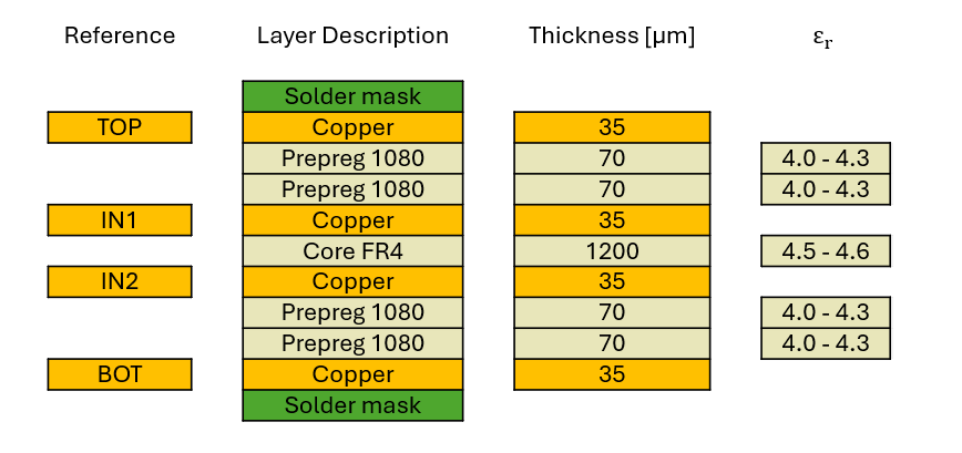
Final Thickness: 1.6 mm +/- 10%
Impedances
The following track layouts can be used to realize defined impedance. Please note that these values only provide a basic orientation. Interference factors such as angles, meanders or vias in the routing of the tracks may negatively affect the intended impedance.
| Type | Resistance [Ω] | Signal | Reference | Width [µm] | Space [µm] | Width [µm] |
|---|---|---|---|---|---|---|
| SE | 50 | TOP | IN1 | 295 | - | - |
| DP | 90 | TOP | IN1 | 260 | 135 | 260 |
| DP | 100 | TOP | IN1 | 220 | 150 | 220 |
| SE | 50 | BOT | IN2 | 295 | - | - |
| DP | 90 | BOT | IN2 | 260 | 135 | 260 |
| DP | 100 | BOT | IN2 | 220 | 150 | 220 |
SE = Single Ended, DP = Differential Pairs