Project: Sandbox / vacant by Die Dosen Stapler at AISLER
Page on our website: DDoS
We are a robotics team competing annually at the Eurobot competition.
The theme changes yearly, but always involves similar components:
suction cups with vacuum pumps, servo motors, and stepper motors.
Rather than design a large PCB with all the components needed for the current year’s challenge,
which will become obsolete for the next competition,
we are developing reusable modules that we can combine into any configuration we need.
For example, this year our robot will have 4 suction cups with four vacuum pumps.
All we need to do is combine 4 of our vacuum pump modules and connect them to the robot’s CAN bus.
Introducing VaCANt
Indeed, the first module we developed was a vacuum pump controller.
We admit that this module is overengineered.
The simplest goal of turning on and off a vacuum can be achieved with a simple digital signal from our main computer.
However, our CAN-powered board offers many more features.
Using an addressable bus means we don’t need a separate signal wire for each pump.
With its onboard current sensor, our module is able to measure the current drawn by the pump.
Since the current goes up when an object attaches itself to the suction cup,
we know whether we successfully picked up the game element.
Finally, this board was a proving grounds allowing us to try many new things.
Most notably, it was our first board with an RP2040, proving our hardware design with this chip
and proving the can2040 library, a fantastic CAN controller implemented in the RP2040’s programmable I/O.
Yes, it’s overkill, but after all, we compete in Eurobot to learn and have fun, not to solve every task in the most efficient way possible.
The vacuum module is called VaCANt.
This name shares its first three letters with “vacuum”,
includes “CAN” like the used communication bus,
and is a word meaning empty, since this board can detect if no game element was grabbed.
Hardware design
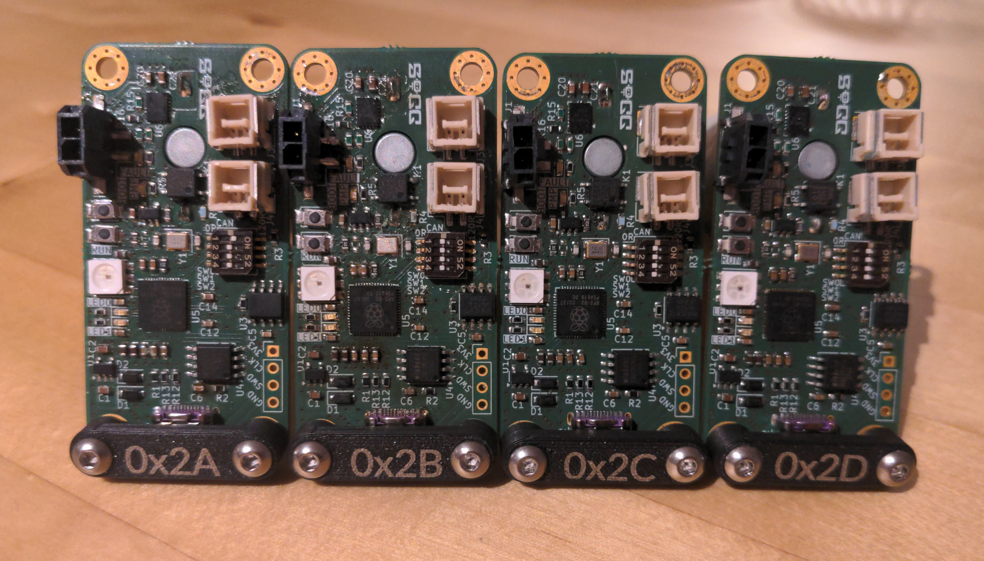
As already mentioned, the star of the show is an RP2040.
It’s a fairly typical implementation; we didn’t deviate from Raspberry Pi’s hardware design guidelines,
using their recommended FLASH, oscillator, decoupling capacitors, and strapping.
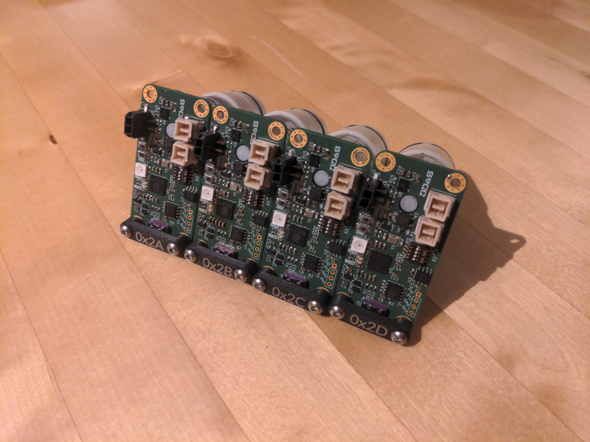
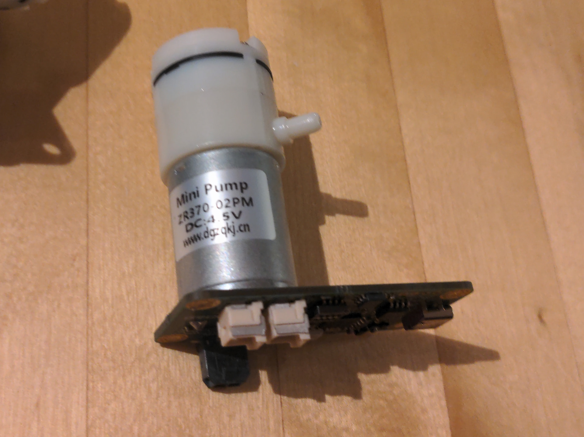
The small vacuum pump is soldered directly to the PCB, simplifying wiring and keeping everything compact.
It’s turned on and off through a solid state relay,
and a shunt resistor and INA180A2 current-sense amplifier measure its current draw
and make this available to an analog input of the microcontroller.
The board is powered through a Micro-Fit connector.
An e-fuse (TPS25940) protects against reverse polarity, overvoltage, and undervoltage
and provides current limiting and soft start.
The SN65HVD230 is used as the CAN transceiver.
We selected this one because it operates on 3.3V and because we had good success with it in the past.
Two CLIK-Mate connectors carry the CAN signals, and are duplicated to allow daisy-chaining.
An APA102 SPI RGB LED shows the status of the board,
indicating states like “ready”, “connection error”, “sucking a game element”, or “sucking air”.
A four-position switch is included to connect and disconnect the CAN termination resistor
(disconnected for daisy-chaining, connected if it’s the last node in the chain).
We planned to use the other 3 positions to set the CAN address, but in the end we did this completely in software.
CAN bus
The primary reason we chose the CAN bus is that it’s the protocol
our main computer already uses to communicate with our ODrive motor controllers
responsible for propelling the robot.
Even without this motivation, CAN would still have been an appealing choice.
It’s extremely robust and allows for a large number of nodes to communicate
at high speed over a single differential pair.
The software and hardware support makes CAN very approachable.
We opted to send our messages using raw CAN messages
rather than using an abstraction like CANopen or cansimple,
although our protocol works similarly.
CAN messages include an 11-bit address.
However, the address doesn’t necessarily have to uniquely identify a node.
We use the top 6 bits of the address for the node ID and the bottom 5 bits as the command,
where the command could be something like turning the pump on or requesting the current reading.
CAN autodiscovery
To allow ourselves to reconfigure our bus from software,
we implemented an autodiscovery procedure.
The first time a board is powered on, it will have the default node ID 0x2f.
Without changing this, it would not be possible to control the pumps individually.
Furthermore, the boards would not be allowed to publish any data, as doing so would incur a large risk of an addressing conflict, which is forbidden on the CAN bus.
Therefore, it’s necessary to assign unique node IDs to each module.
With our procedure, it’s possible to do this over CAN, without any hardware changes, without re-flashing firmware, or plugging in a second configuration interface.
The problem is, how can we instruct a single node to take a new node ID when it shares its current node ID with others?
Any message we send to one node will be sent to all nodes.
The trick is to use the serial number.
We send a message with the default node ID and with a command instructing them to introduce themselves.
Each node replies (after a random delay, to reduce the risk of conflicts) with its serial number.
Then, we can send commands to individual nodes using their serial number.
The default node ID is still used, but the message data is the serial number of the node we want to address.
We send such a command to the first received serial number telling the corresponding node to start flashing its LED,
allowing us to identify it visually.
Our script then asks us to enter the desired node ID of the flashing node.
We send a final command instructing the flashing node to change its node ID to whatever was input.
This is saved on the FLASH chip, and the module starts listening on the new ID.
This is repeated for the remaining received serial numbers.
msg(node_id=0x2f, cmd=INTRODUCE)
msg(node_id=0x2f, cmd=INTRODUCE_RESPONSE, data=sn1)
msg(node_id=0x2f, cmd=INTRODUCE_RESPONSE, data=sn2)
...

msg(node_id=0x2f, cmd=FLASH, data=sn1)
<user enters new node ID: 0x2a>
msg(node_id=0x2a, cmd=SET_NODE_ID, data=sn1)
Next steps
In this post, we presented our idea for composable CAN modules
and presented the first: VaCANt.
We already created the second module, a stepper motor controller,
which will be the subject of a future post.
We have plans for many more modules,
such as servo motor controllers, angle sensors using diametric magnets,
and general input/output modules (digital, analog, I2C).
Thanks to Aisler for these Beautiful Boards.