Project: Sandbox / centipede by Die Dosen Stapler at AISLER
Page on our website (with 3D viewer, KiCad viewer, and iBOM): DDoS
Source files: Die DOsen Stapler / Evergreen / PCBs / Centipede · GitLab
In our last post,
we kicked off our system of composable modules for the Eurobot robotics competition
by introducing the VaCANt smart vacuum controller.
In this post, we move on to the next module: a stepper motor controller.
On the surface, it’s a simple motor controller.
In reality, this board is also an opportunity to test new components that prove to make our modules smaller,
not only allowing this board to be compact, but also enabling future modules that wouldn’t otherwise be possible.
We have plans for much smaller modules that wouldn’t make sense without minifications.
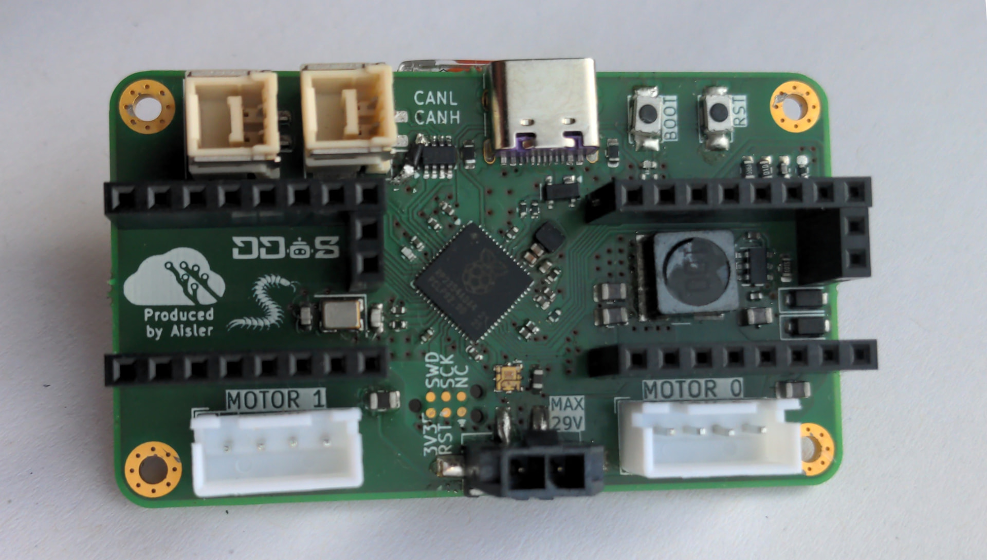
Introducing Centipede
Our second module is a stepper motor controller called Centipede.
The name comes from the fact that centipedes have a lot of legs, and take a lot of steps.
This board receives commands from the robot’s main computer and asynchronously
controls two stepper motors with the requested position, velocity, and acceleration.
Hardware design
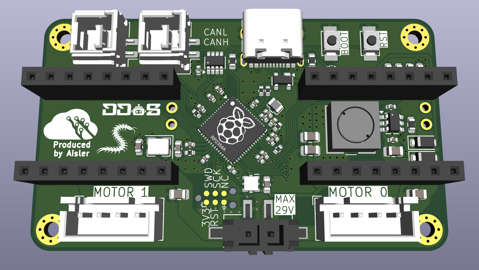
The first new smaller component is the microcontroller.
Rather than the RP2040 we used in VaCANt,
for this board, we used the new RP2354.
This chip has built-in FLASH storage, removing the need for an external module.
Not only was this one of the largest components on the previous boards,
but reduces component count, simplifying assembly and reducing cost.
Integrating the RP2354 is quite similar to the RP2040.
The most notable difference is in the way the 1.1V rail is generated.
Where the RP2040 has a build-in linear regulator,
the 2354 has a buck converter that requires and external inductor and capacitors.
This change improves efficiency, but requires special care in the layout
to achieve good performance and low noise.
The 2354 has many other new features compared to its predecessor,
mostly related to security, none are relevant for our application.
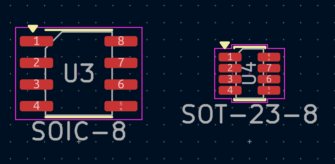
The next space-saving measure is the change of our CAN controller
from a SOIC-8 part to the SOT-23-8 TCAN3414 (see image below for a size comparison).
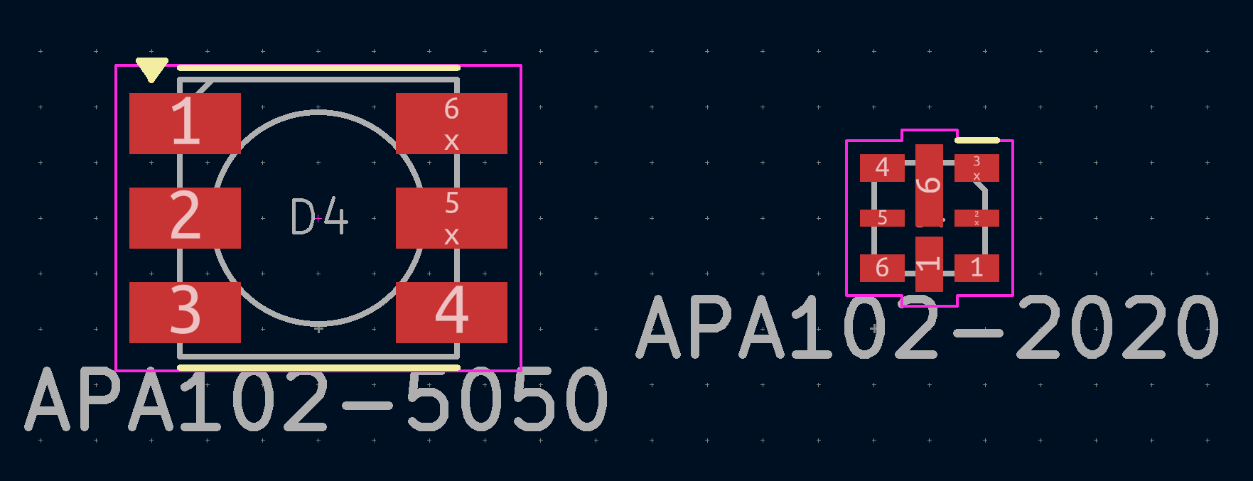
Next, we changed the APA102 RGB LED from the 5x5mm package to the 2x2mm package.
Since we have a CAN autodiscovery protocol,
we removed the four-position switch for setting the CAN address.
Finally, although this board has a USB connector, it additionally uses the componentless Tag-Connect programming connector
(componentless meaning that the PCB only has exposed pads, no soldered component).
Validating this as a programming method allows us to omit the USB connector in future designs.
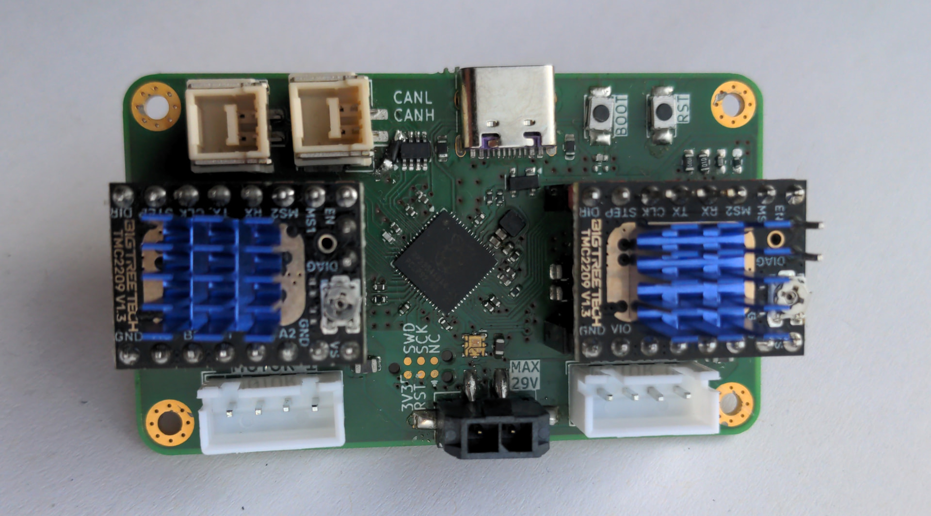
Being a stepper motor controller, this board has two sockets for TMC2209 stepper motor drivers.
One of the nicest features of these drives is that they are configurable over UART.
The motor current, microstepping, and chopping mode can all be configured through software.
It’s very nice to not have to go poking around in the robot with a screwdriver trying to set the current limit using the tiny potentiometer on the driver.
The power input connector expects relatively high voltages to supply sufficient power to the motors.
This needs to be stepped down to 3.3V to power the microcontroller and other low-voltage circuitry.
To do this efficiently, a buck converter (TPS54202H) is used.
Next steps
This post has shown the many ways we minified our CAN modules.
We have plans for small modules such as sensor.
Without the need for external FLASH, a USB connector, or address switches, they can be truly tiny.
Stay tuned for our sensor modules!
Thanks to Aisler for these Beautiful Boards.