In mid-October, the first bi-liquid rocket from ARIS, HERMES, attempted its maiden launch at EuRoC 2025. Today, we want to give you an introduction to the electronics necessary for the engine and the special conditions those electronics needed to withstand.
For more information about the entire avionics setup of the rocket, you can look at our last post, going into detail about the entire Avionics structure of the rocket.
Our engine control system consists of three boards:
-
Fuel Control Board (FCB)
-
Oxidizer Control Board (OCB)
-
Engine Control Unit (ECU)
Originally, the plan was to have two distinct PCB designs: one board design (referred to as the Pressure Control Board) used twice and programmed as either the FCB or OCB, and a separate design for the ECU.
Pressure Control Board
The physical PCB is identical for both the fuel and oxidizer control boards. This distinction only becomes apparent upon flashing the corresponding firmware onto those boards.
All pressure control boards are capable of the following:
-
Reading out up to four digital pressure transducers via RS-485
-
Reading out two Thermocouples, with Cold Junction Temperature compensation enabled by a thermistor
-
Switching three 24 V solenoid valve outputs
For the solenoid outputs, fast switching times are important, as our tank pressures are controlled via a dynamic pressure reducer (DPR), which is functionally a bang-bang controlled solenoid valve. This enables us to adjust our tank pressures during flight to throttle the rocket engine and follow an ideal thrust curve.
Thus, the Fuel and Oxidizer Control board both monitored tank pressures (for the N2 and Ethanol tank, as well as the LOx tank, respectively), monitored tank temperatures and regulated tank pressures according to commands from the Flight Computer or Engine Control Unit, either via the DPR or via the Vent valves.
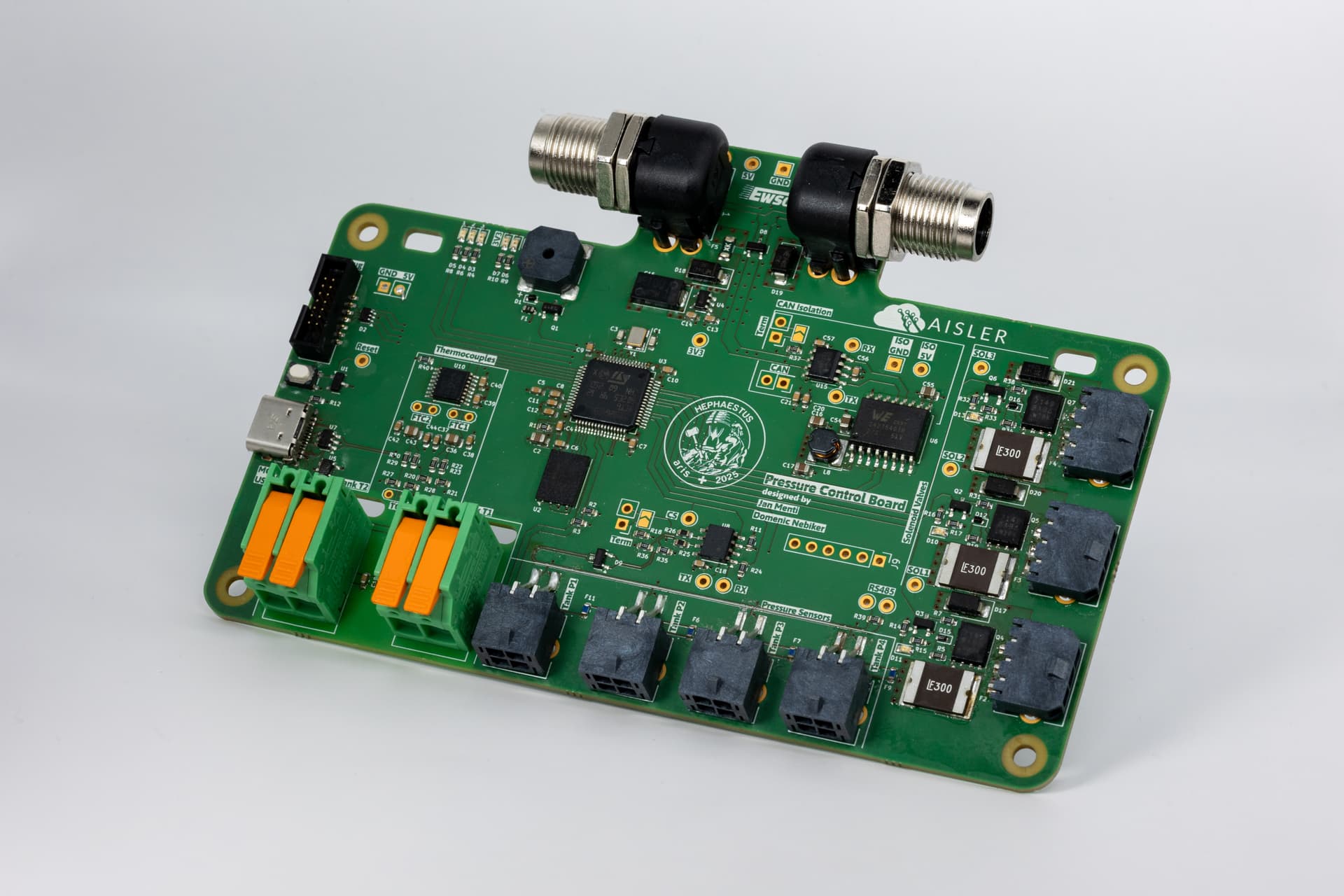
Pic 1: Pressure Control Board
Engine Control Board
The originally intended ECU was a bit different. We intended to develop our own main valves. These would have needed an electric motor as an actuator, so the ECU provided functionality for integrating electric motors. The power to the motors could be cut using an arming Pin, as per EuRoC regulations.
At the same time, the ECU was fitted with three channels for sensing 4-20 mA analog pressure transducer outputs, as we wanted to use the same pressure sensors on the engine as were already used on our test bench.
It additionally featured the same electronics for temperature sensing as the pressure control boards.
During Engine operations, the ECU would command both the FCB and OCB, monitor combustion chamber and injector pressures, and operate the main valves as part of the firing sequence or upon direct command from the Flight Computer.
Pic 2: Original Engine Control Unit
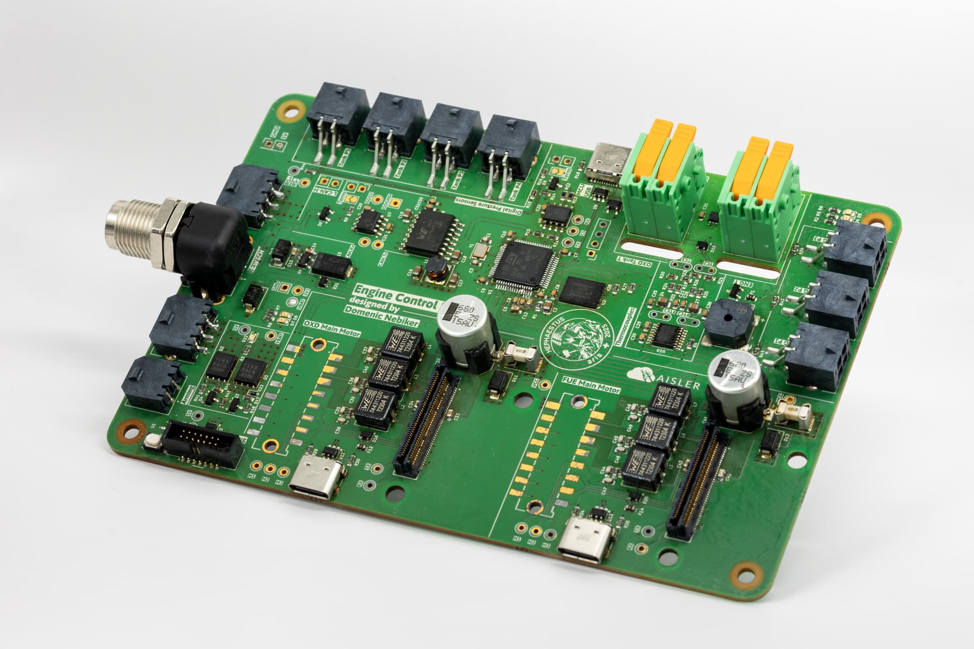
However, several months before the competition, it became clear that we would not be able to develop our own cryogenic main valves in time. We switched to solenoid valves instead, which made the ECU hardware unnecessary. As a result, we replaced it with a slightly modified pressure control board (speaking that we soldered an arming assembly onto it).
Pic 3: Pressure Control Board modified to act as ECU
Issues at Cryogenic Temperatures
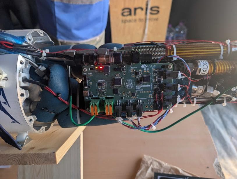
We use liquid oxygen as our oxidizer. Combined with the severe space constraints of a rocket, this meant that two of our PCBs had to be able to operate in cryogenic environments. The ECU was especially heavily affected by it as it is mounted immediately below the LOx tank inside a carbon fiber faring, which does not allow any airflow across the PCB to heat it up. During testing, the air temperature next to the engine control board got as low as -130° C.
Electronics assemblies are almost never rated for such low temperatures, so we had to approach this carefully.
Our first major concern was not the cold itself but condensation. This is a result from chilling the entire air both above and below the oxidizer tank. This was mitigated by utilizing several layers of conformal coating. This ensured that no water could short out any component on the PCB itself. However, we still needed to get connections away from the boards – either for our main wiring harness, or to connect to valves, pressure sensors or thermocouples. As such, these connections were either IP rated, or just filled with glue on the cable side, preventing trapped air being present in the connector that could lead to condensation.
SMD fuses turned out to be another unexpected problem. Small 0603 fuse packages repeatedly cracked under thermal stress, interrupting power to the pressure sensors. Replacing them with 0 Ω resistors solved the issue and did not cause reliability problems in practice.
Our third, and biggest issue, had mostly to do with electronics and assemblies external to the boards:
We are unfortunately not in possession of pressure sensors rated to below -40°C.
At low temperatures, piezoelectric pressure sensors experience some amount of drift. Our analog ones from the test bench experienced 1-2 bars of drift in cryogenic environments.
Our digital ones implement temperature drift compensation, for which they require active electronics. This means that when they get too cold, they stop responding, necessitating heating of any digital pressure sensor we want to install at the engine. Luckily, this problem is confined to the engine, as above the oxidizer tank temperatures never got that low.
Due to the switch of the main valves, and the corresponding switch of the required electronics, we were unable to use the analog pressure sensors in the engine bay and had to switch to the digital ones. This just resulted in us installing heating pads on every engine pressure sensor, which were controlled by reading out their internal temperatures and switching on the heating if the temperature got too low.
The last big issue was that fuel tended to freeze in our main line. This was solved similarly to the pressure sensors – by adding heating pads to the main line and main valve.
In the end, we achieved a functioning engine control system. On the EuRoC launch pad, we successfully ignited the engine. Unfortunately, an automatic abort correctly triggered shortly afterward, shutting down the engine. A series of subsequent fires destroyed the rocket below the LOx tank, preventing further launch attempts.
However, we can proudly report that the AISLER PCBs survived both cryogenic temperatures and being burned, and the recovered board shown here still works as intended.
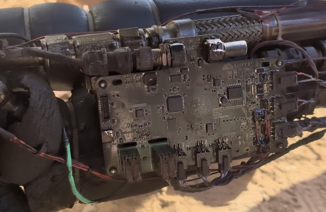
Pic 4: Slightly burnt ECU after the attempted Launch
We are incredibly grateful for having found such a reliable partner on our journey as Aisler, and we would like to thank the entire team for their support in the past few years. Without them, such projects would not have been possible!
If you are interested about further development at ARIS, check out our website, Instagram and LinkedIn. Our follow-up project, ASTERIA, has already begun and aims to finally fly a bi-liquid rocket to 9 km at EuRoC.