We support Target3001! out of the box and prepare your design files for manufacturing using our automated software pipeline. If you have any questions or want to make remarks, please contact our support before ordering, as we do not read notes included in your project files.
Import Target3001! using ODB++
Overview
We support ODB++ files created with Target3001 V32.2.0.29 and newer. The use of the ODB++ format allows for the auto assignment of components, which is not supported when uploading the Target3001! project file.
Design Remarks
We prepare your design files for manufacturing using an automated software pipeline, if you have any questions or remarks contact our support before ordering, as we do not read notes included in your project files.
Preparations before exporting
Open up your PCB file and make sure all planes and polygons are updated, make sure to run the DRC to catch any errors, if there are any, please resolve them. Save your design.
Export of the ODB++ file
Open the PCB Editor and navigate to: File -> In-/ Output Formats -> Production -> ODB++
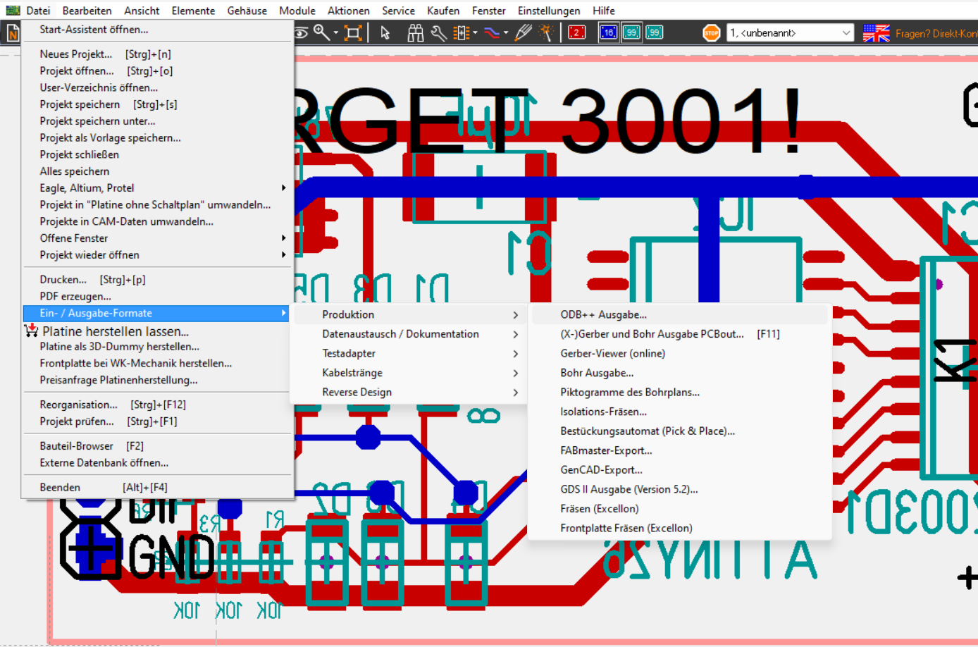
This will open up a new window where you can select where you would like to save the ODB++ file.
Import of the ODB++ file
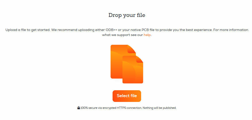
You can upload the ODB++ file via drag and drop on the startpage or the Import Project button in the project overview.
After we processed the board file you can inspect the boards using our board viewer.
We give a rendering guarantee that the boards are manufactured as displayed in our viewer. You can read this article if you are unsure how to use our board viewer or if you want to know how the rendering guarantee works.
Importing Target3001! files by uploading them to AISLER directly
Luckily we support Target3001! natively, so the steps are very very simple ![]()
Step 1: Upload your Target3001! file
We support Target3001! file format natively. Just Drag’n’Drop or Upload your Target3001!-Board file and you are good to go.
Step 2: Profit 
Setting the correct mount types of a component within Target3001!
Abstract
Knowing how a component is mounted is information we use to plan and calculate the assembly, so it is required to include the mount type in your production files.
Mount types
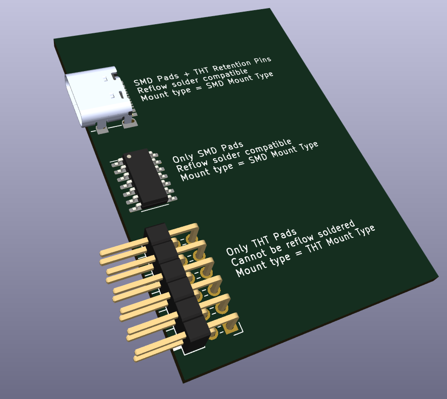
We categorize components into SMD or THT parts.
SMD/ Surface Mount Components are placed on one side of the PCB, they can be populated using a pick and place machine and reflow soldered, this makes them very economical.
THT or Through Hole Technology describes components whose pins/leads are inserted into the PCB and soldered to contact on the other side. They are more sturdy and thus better suited for mechanically demanding applications, but they cannot be placed with a pick and place machine and require special solder processes like wave or selective soldering.
Some components like USB-C connector have both surface mount pads and trough hole retention pins, as it is possible to reflow solder these components they can be categorized as SMD part.
We can summarize: A component is categorized as SMD when it mounts to one side of the PCB and can be reflow soldered. Parts with leads through the PCB that cannot be soldered using reflow are categorized as THT parts.
You can contact our support if you are unsure which option you should choose for your component.
Update an existing footprint
An existing footprint with a mismatching mount type can be easily updated.
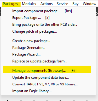
Open the schematic view and select Packages -> Manage components (Browser)... or press F2.
Enter the name of the part of which you want to update the mount type in the search bar and press the search button. Select the component in the search results.
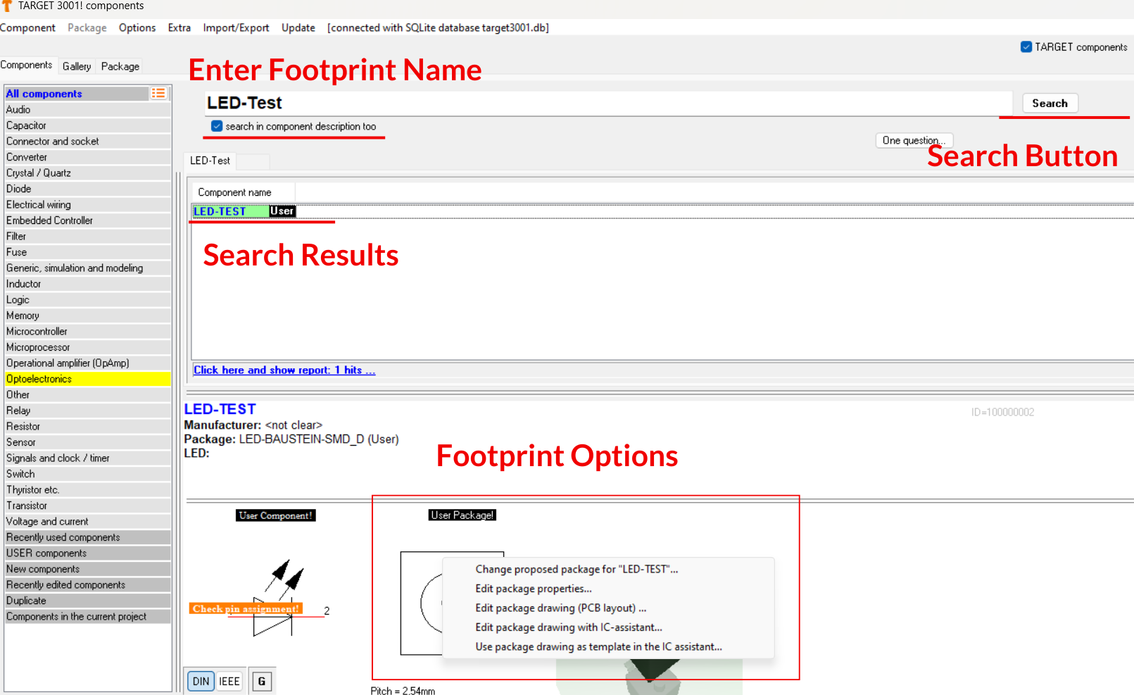
At the bottom, an overview of the Symbol, Footprint and 3D model will be displayed.
Right-click on the footprint to open a context menu, then click on Edit package properties.

Check or uncheck the SMD checkbox based on the guidance we provided.
Click Save after you applied the changes.