Four Motors, One Power PCB: Our Second-Generation SiC Inverter
Hello fellow makers,
We are Campus Tirol Motorsport, the Formula Student team from Innsbruck. Every year, we develop and build an electric race car to compete against university teams from around the world. You can learn more about Formula Student and our team.
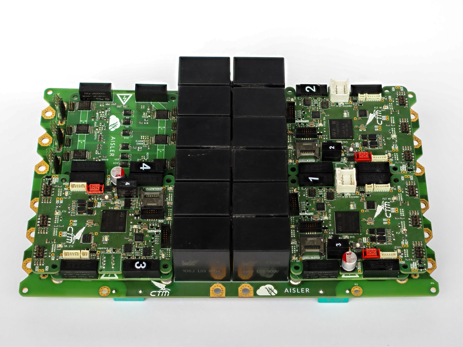
In our previous article, we introduced our first self-developed motor controllers: modular assemblies separating the power stage, gate drivers and control electronics. For the second revision, we focused on three areas: more compact packaging, greater processing capability and a redesigned phase-current measurement system. The result combines all four inverter power modules on one shared power PCB, saving 20% of the installation space compared with the previous arrangement.
Four independent drives, one shared power PCB
Our drivetrain uses four interior permanent-magnet wheel-hub motors, each driven by its own three-phase inverter. The design operates with a 600 V battery, with a peak power of 35 kW per motor. Although the power modules now share a PCB, each motor retains its own independently controlled three-phase bridge.
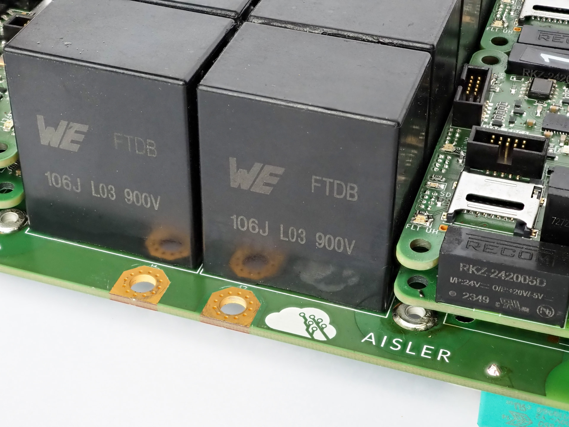
The new power board integrates four Infineon FS13MR12W2M1H SiC MOSFET modules and their common DC link. Twelve 10 µF, 900 V capacitors provide 120 µF of nominal bulk capacitance, supplemented by local ceramic decoupling at the individual inverter stages. Consolidating the four power assemblies lets us use the available installation space more efficiently while retaining separate gate-driver and control electronics.
With SiC, the interconnections are as important as the switching devices. High di/dt produces voltage overshoot across parasitic commutation-loop inductance, while high dv/dt creates demanding conditions for isolation and signal integrity. Keeping the DC-link decoupling close to the power modules and the switching-current loops compact therefore remains central to the design. A shared DC link also makes the interaction between the four switching stages an important consideration.
A new STM32H7 control platform
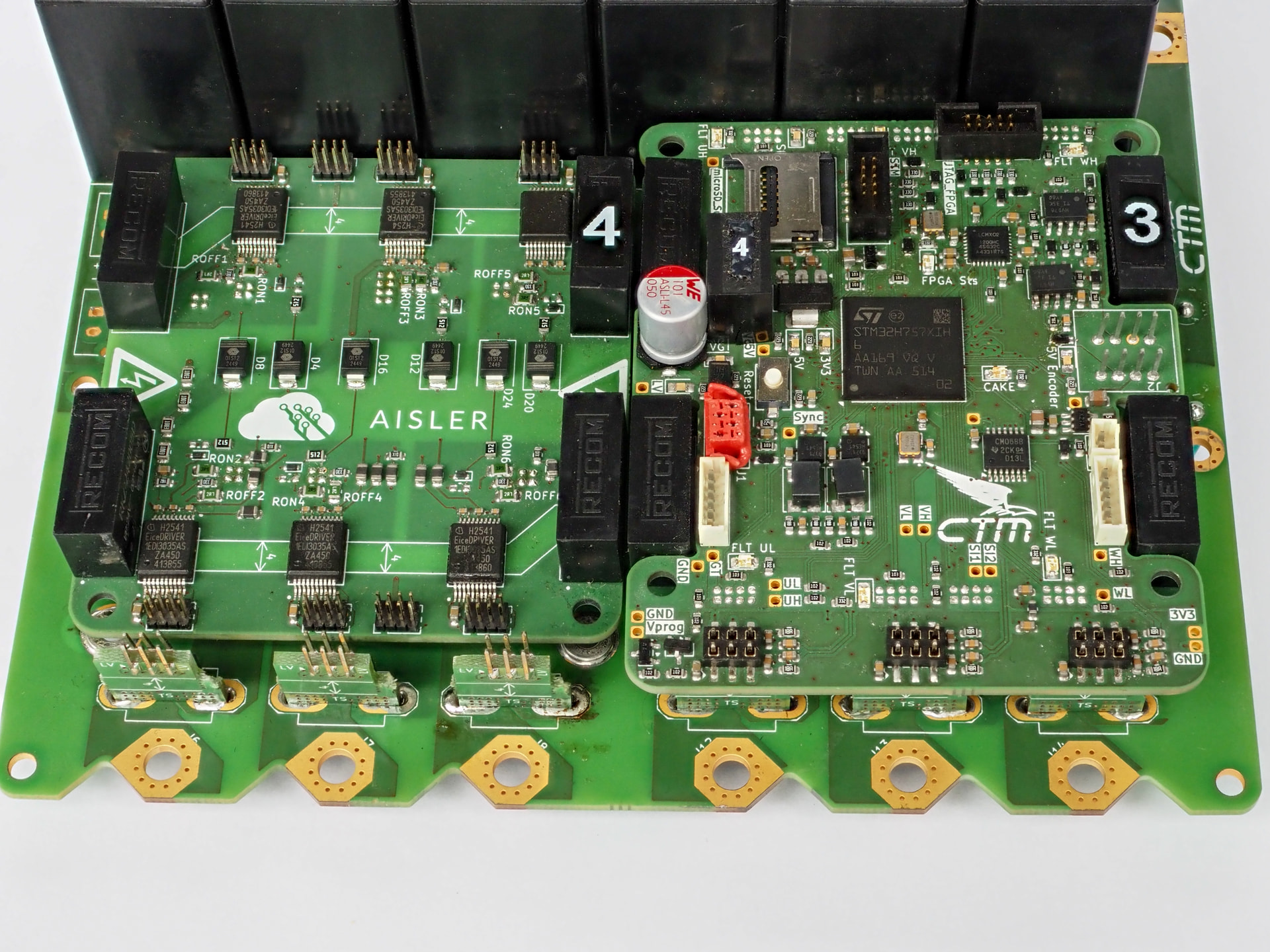
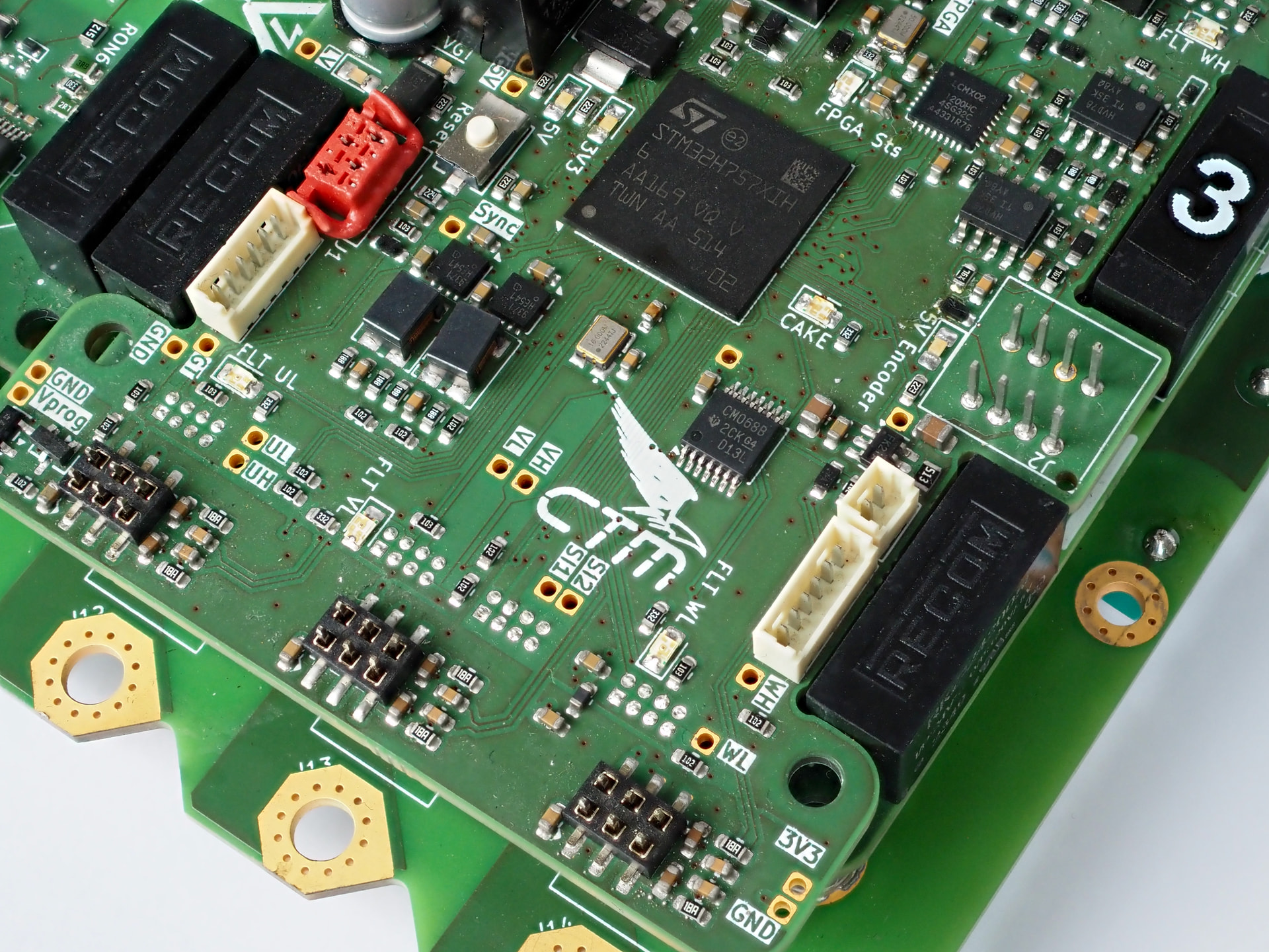
The redesigned control board replaces the STM32G474 with an STM32H757XIHx. This dual-core device combines a Cortex-M7 capable of up to 480 MHz with a Cortex-M4 capable of up to 240 MHz, providing substantially more processing headroom for field-oriented control, diagnostics and communication. It also offers the option of separating time-critical control from supporting tasks across the two cores.
The phase-current channels connect to differential inputs on the MCU’s three ADCs, while TIM1 provides the complementary PWM outputs for the three half-bridges. Gate-driver fault signals are combined in external logic and routed to TIM1’s break input, providing a hardware path for disabling PWM without waiting for a software polling cycle.
Operating modes and control setpoints continue to arrive over CAN FD. In addition, a separate synchronization connection uses a second CAN transceiver as a physical interface to the MCU’s timer signals. This provides a hardware basis for coordinating switching timing between the four inverters, independently of normal CAN message traffic.
We retain a dedicated FPGA for the encoder interface. The Lattice LCMXO2-1200HC-4SG32C communicates with the STM32 over SPI, while two SN65HVD78DR transceivers handle the differential clock and data lines. A microSD interface connected through four-bit SDMMC provides local logging for development and testing.
Redesigned phase-current sensing
The new current-sensor PCB is built around Infineon’s TLI4971-A075T5-U-E0001, a coreless magnetic current sensor with a ±75 A measurement range and a typical bandwidth of 240 kHz. Its differential magnetic sensing principle helps suppress external stray fields—particularly relevant when twelve phase conductors and four switching stages share a compact assembly.
For each phase, both the sensor’s analog output and its reference voltage are routed to the control board and filtered before reaching a differential ADC input pair. The 220 Ω series resistors and 15 nF ADC-side capacitors define a nominal RC pole of approximately 48.2 kHz, with additional capacitance on the sensor side. This makes the analog input filtering an explicit part of the measurement design rather than relying solely on the sensor’s bandwidth.
The sensor also provides two fast overcurrent-detection outputs. These are brought back to the controller on dedicated fault lines, making overcurrent indications available independently of the regular ADC measurements. Together, the analog feedback and fault outputs support both current regulation and fault handling.
Updated gate drivers and protection
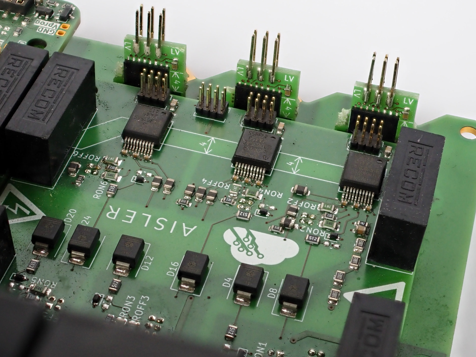
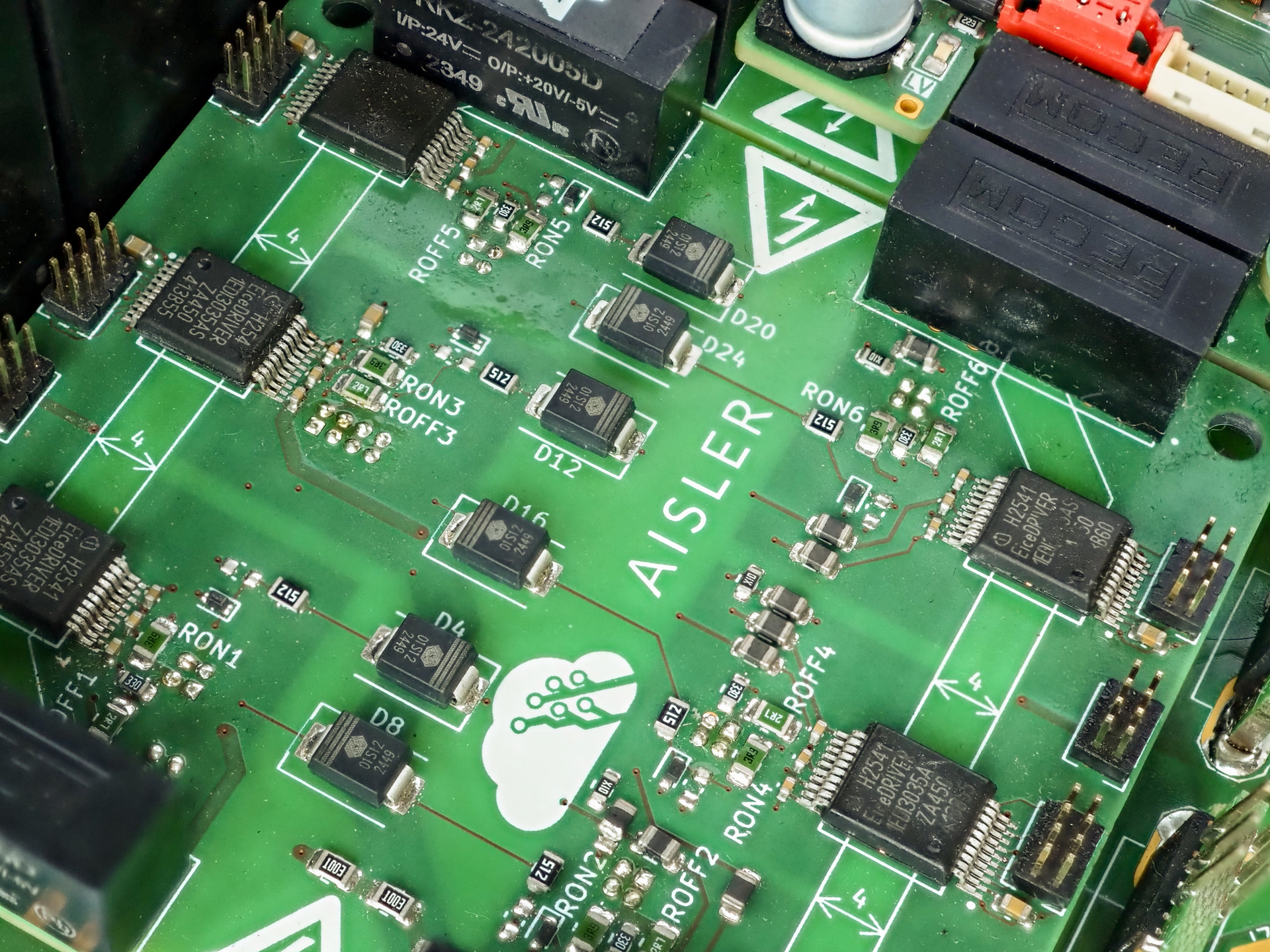
The gate-driver design now uses Infineon’s 1EDI3035AS, an isolated SiC MOSFET driver with desaturation protection and up to 20 A peak output capability.
Separate turn-on and turn-off paths use individual 5.1 Ω gate resistors, allowing the two switching transitions to be tuned independently. A dedicated soft-turn-off path uses a 33 Ω resistor for controlled fault shutdown. The design also uses a negative gate-bias rail, while ready, fault and diagnostic-data connections link the drivers to the control board. This keeps switching control, local device protection and system-level fault reporting closely integrated.
Developed with AISLER
AISLER has been our main PCB supplier since 2021 and continues to support the development of our in-house electronics. Their online Gerber viewer, support for native KiCad board files and revision-management tools make it straightforward to move from a design update to the next manufactured board. Reliable PCB quality and short turnaround times are especially valuable when power electronics, measurement circuits and control hardware are being developed together.
This second revision brings our four motor drives into a more compact assembly and provides a stronger platform for control and measurement. We would like to thank the entire AISLER team for their continued support and for helping us turn another generation of in-house inverter development into hardware.