We guarantee that your boards are assembled as rendered in our Assembly Viewer. For a successful assembly, it is key to inspect the data before ordering to avoid mistakes. In this guide we explain how to interpret the information displayed in the viewer.
Lets start an overview of the Interface:
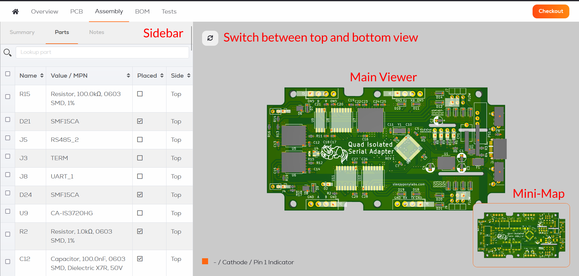
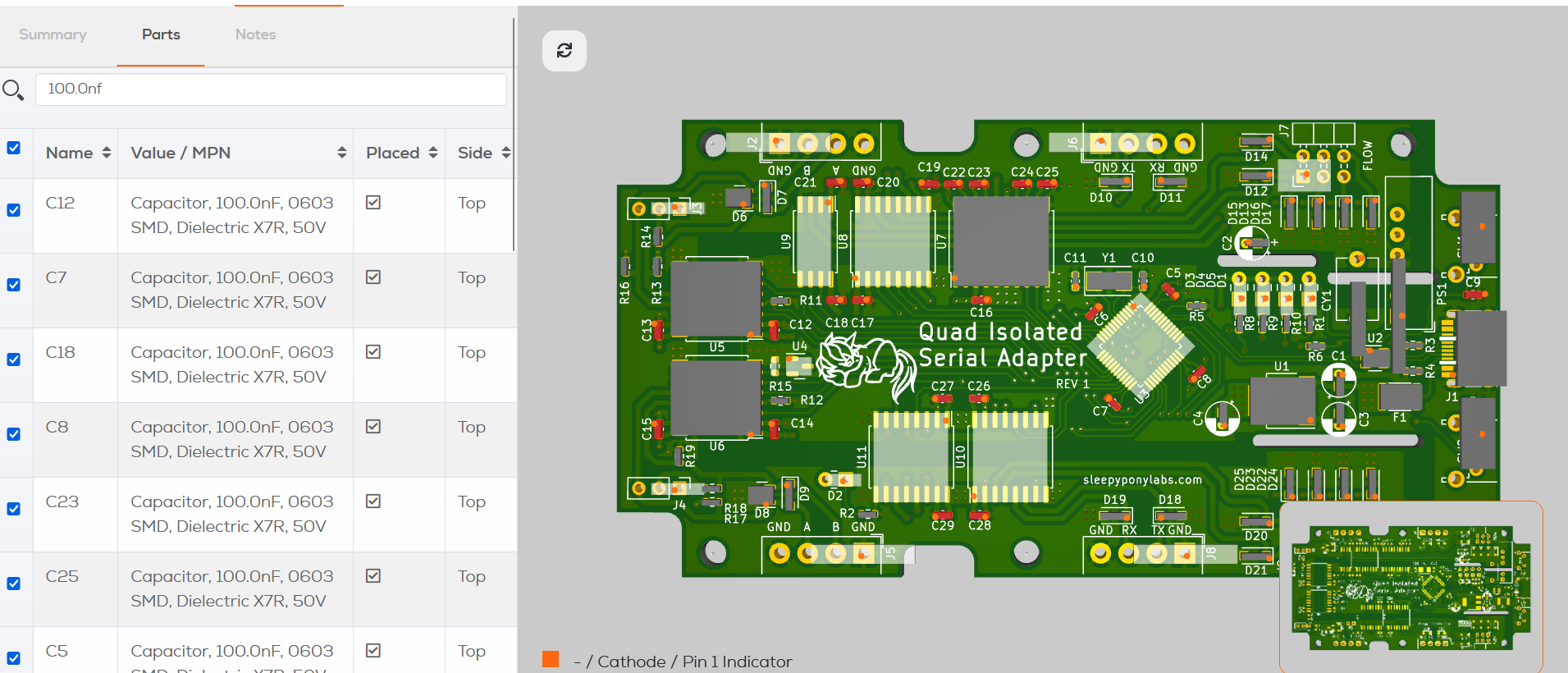
The interface is split into two halfs, on the left you have the Sidebar with multiple tabs, the
Parts tab is displayed by default. On the right we have the main viewer. You can rotate the view using your mouse, we also added a button in the top left corner to switch between top and bottom view in case you are using a trackpad.
The Sidebar:
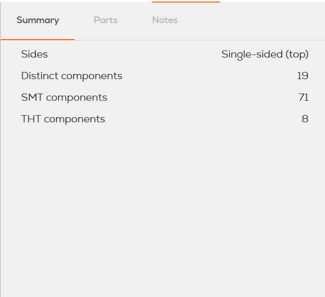
The Summary tab in the sidebar gives you an overview of your project, it lists the amount of distinct components and how many of them are THT or SMD.
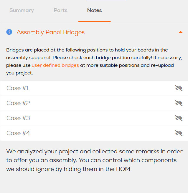
Warnings or productions notes like the placement of your custom bridges will be displayed in the Notes tab.
The Parts tab is displayed by default, there the components of the bill of material will be displayed. You can search for a specifc component using their designator or component value.
Components can be highlighted using the checkbox on the left side or by clicking on them in the viewer.
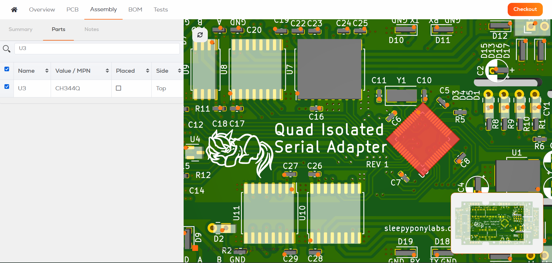
If there components with a common value you can highlight them as group, like in this example all the 100nF decoupling capacitors or individually.
Inspecting the Board
When taking a look at the assembly viewer you will see 3D bodies placed on the footprints. These are based on the pad layout and are a approximation, so use them only as basic reference.
Components which are assigned and included in the BOM are displayed in a opaque gray tone, only these components will be placed on the board. Components which are not yet assigned or excluded from the board are displayed in a translucent white tone.
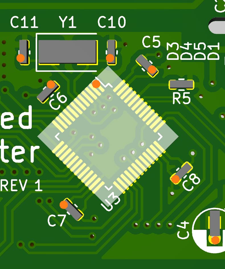
When components have more than 2 pads, their first pin is indicated by an blue marker.
Polarized components like capacitors and diodes are marked according to our. Assembly Polarity Rules .
It is especially important to check the polarity, if you think there is an error contact our support.
Checklist for a successful assembly:
- The BOM lists the correct MPN for the components to be placed.
- All components you want to be placed on the board are displayed in opaque gray.
- The Pin one indicators and polarity indicators are all correctly placed.
We will manufacture the board using the displayed information, it is your responsibility to provide and check the manufacturing data, so you will receive a working board.
When placing an order, we will create a snapshot of the data we were provided with, from which we then create the manufacturing package. In case you find an error regarding the PCB, BOM, stencil or component polarity, contact our Project Management Team as soon as possible, changes made in the Web Interface will not be taken into account.
In case we make a mistake and your board is not assembled according to the data you provided, you are entitled to a rework/remanufacturing of the boards or a refund.