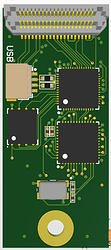
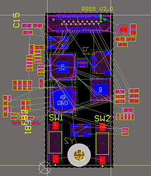
Hey, my name ist Leonard and in this post, I want to present my Design Developing Process of a Speed Sensor PCB. I participate in a student racecar construction project and we use Altium for our PCB Design. I like electronics, because you can implement crazy stuff in small spaces and nowadays there are no limits, even for non commercial student projects.
I want to share my Altium Design experience with you. Important to know: The PCB is part of several PCBs placed in one housing. The communication between the PCBs is realized with a Pin Header. Of course, the position of the Pin Header is fixed, so I needed to keep that in mind while arranging all the other components.
The same applies to the Board Outline and a screw hole. Before I started arranging the components, I took a look at which bus systems exist between my IC’s. This helped to place the Components in an efficient way.
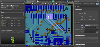
Check out the net class feature Altium provides you with. This gives a good overview about the different netsystems.
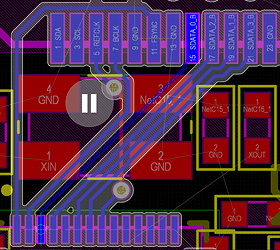
The first nets I routed were the differential nets. My design only had one differential net: USB. I rearranged my PCB structure slightly to keep the trace for the differential net as simple and short as possible.
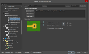
Then I routed the other bus systems. I tried to keep the ways as short as possible and I kept a little distance between the clock trace and the data trace. This should reduce the interference in the bus system. Then I routed all the other smaller components, mostly resistors and capacitors. Most of the capacitors were used to decouple the IC’s, so I placed them directly under the IC’s (on the other side of the board). After that I routed all ground and supply traces. That’s quite easy because my design has four layers. Sometimes, I also use the middle layers for data traces, but normally I use them as power and ground plane. My last step was to arrange the Design Rules according to Aislers fabrication limitations and run a design check. In order to not violate the minimum solder mask width, I had to tend some of my vias. I always tend the vias under components and the Power/Ground Vias. Reason for that: Vias under components cannot be reached after the component is placed, so you cannot use them for measurements on your PCB while debugging. Instead, you risk having some solder bridges under the component and I assure you, that you won’t find them. I have another tip: You can create some special rules in the Design Rule Panel. I created one, to tend all GND and Power Vias, so I didn’t have to tend them one by one.
Last but not least: A colleague checked my design. I highly recommend such a review system, because it helps to spot mistakes before the PCB is fabricated. Also don’t forget to let someone check your schematics before starting the Layout.
Finally, I generated the Fabrication Output Files: Gerber File and NC Drill Files. Don’t forget to hit the “generate separate NC drill files for plated & non plated holes”. Aisler needs this information separately. Afterwards I renamed the Gerber and NC drill files according to Aislers standards. Checkout this Aisler Information Page on how to import the Files to your Aisler Sandbox. Once your design is uploaded, Aisler has a few practical features to check your design. The tool is quite clear and easy to understand. Don’t miss to order stencils, in the case you want to place your components in a solder oven. The order page on the Aisler Website is convenient, because it is integrated in your project overview as well. Now I wait for the PCBs to arrive. Wait for some pictures of the fully assembled PCB!
This is only the Altium 3D view
