Panel
For Amazing Assembly and Simple Supply, we create panels according to this specification. By default, we utilize bridges with mouse bites.
Other configurations are available upon request.
Contact our project managers for inquiry
Standard dimensions
Our assembly panels have the following maximum and minimum external dimensions.
max. 454.8 mm × 494.8 mm
min. 100 mm × 55 mm
Markings
We add additional markers on the panel frame, here an example depicting a single PCB panel.
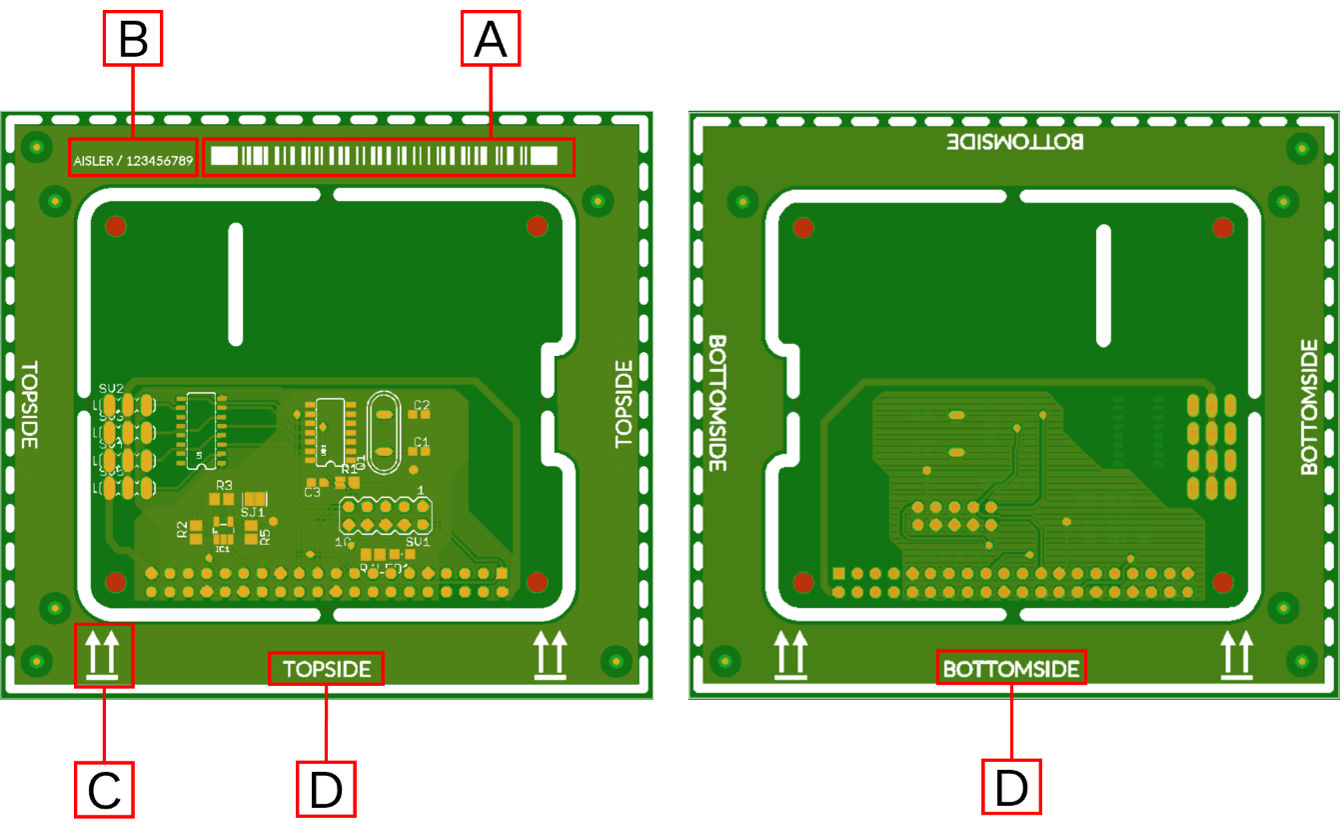
A Barcode
B Order Code
C Panel Orientation
D Top/Bottom
Allocation of boards on the Panel
The number of (individual) PCBs accommodated per panel is determined by us based on PCB size and order quantity. So-called “multi-design” panels (PCBs of different types within one panel) are neither supported nor supplied by AISLER. The individual boards are arranged in rows and columns. The maximum number of rows and columns is limited by the maximum dimension of the panel and the dimension of the PCB. Rows and columns are always populated; no positions are omitted.
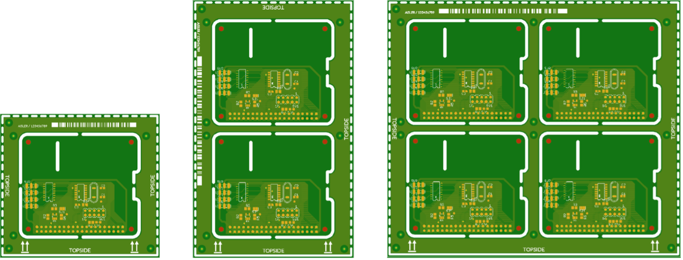
Panels will normally manufactured in multiples of three due to production related processes.
Thus, the sum of delivered individual PCBs may differ from the number of PCBs to be assembled/ordered.
Fiducials
For accurate positioning, we add global and local fiducials on the frame.
Fiducials added on the PCB by the customer will not be taken into account.
Fiducial Geometry
We use the same geometry and size for global and local fiducials.
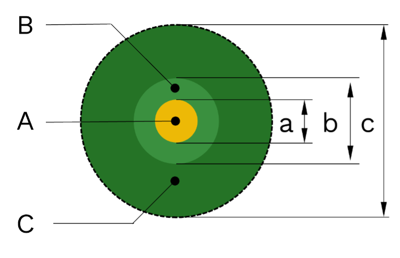
| Reference | Description/Size |
|---|---|
| A | Surface Finish (ENIG / HASL) |
| B | Soldermask Keepout |
| C | Copper Thieving Keepout |
| a | 1,0 mm |
| b | 2,0 mm |
| c | 4,5 mm |
Global Fiducials
We place three global fiducials in the corners of each panel in a triangular arrangement.
The solder paste stencils also feature these global fiducials. On the stencil, the fiducials are laser marked.

The three global fiducials are each placed 5.0 mm (a) from the outline of the panel.
Local Fiducials
Starting from the top of the board (see illustration: TOPSIDE) and with the board in a vertical position (orientation arrows pointing upwards), each individual board has a local fiducal at the bottom-left, top-left, and top-right. All fiducials are located in identical positions (= same coordinates) on the bottom side of the panel. Their arrangement is therefore mirrored when viewed from the bottom side.
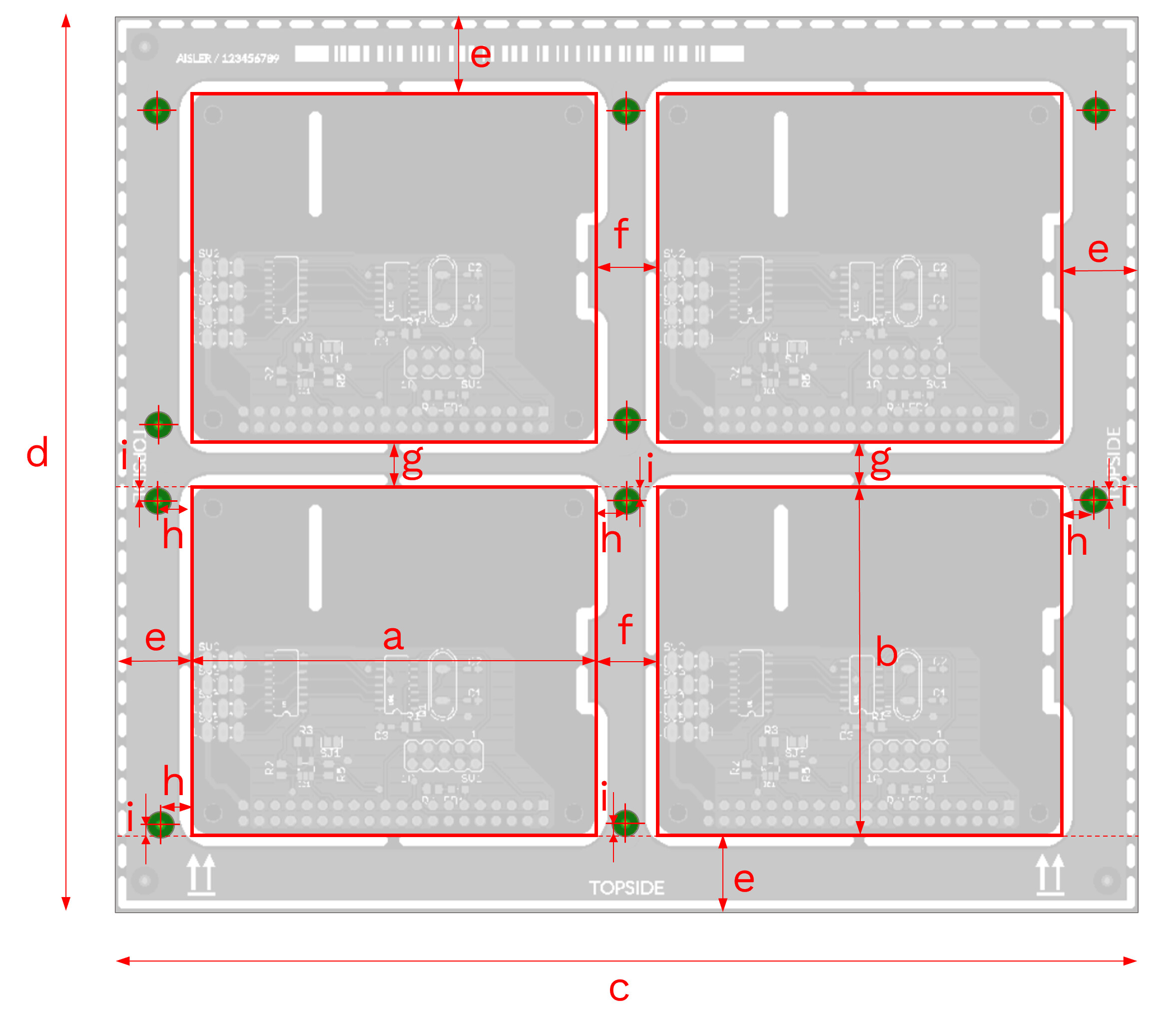
| Reference | Value in mm | Description |
|---|---|---|
| a | variable | Width of PCB |
| b | variable | Height of PCB |
| c | variable | Width Panel |
| d | variable | Height Panel |
| e | 12,4 | Width Panel Frame (horizontal and vertical) |
| f | 9,8 | Horizontal distance between PCBs |
| g | 7,3 | Vertical distance between PCBs |
| h | 4,9 | Horizontal distance PCB → Center point local Fiducial |
| i | 2,5 | Vertical distance PCB → Center point local Fiducial |
The dimensions given above refer to a rectengular bounding box enclosing the PCB
(reference a x b). These dimensions do not necessarily correspond with the shape of the board.