Polarity Detection for Assembly
This article explains how we interpret and display part polarities and what you can do to comply with our polarity rules.
Important: This article is mainly relevant if you’re planning to use our assembly service.
If you’re only ordering PCBs or stencils, you can proceed with your order without considering this information.
Quick Summary
- Before ordering: Please ensure that the polarity marker of each polarized component points to the correct pad.
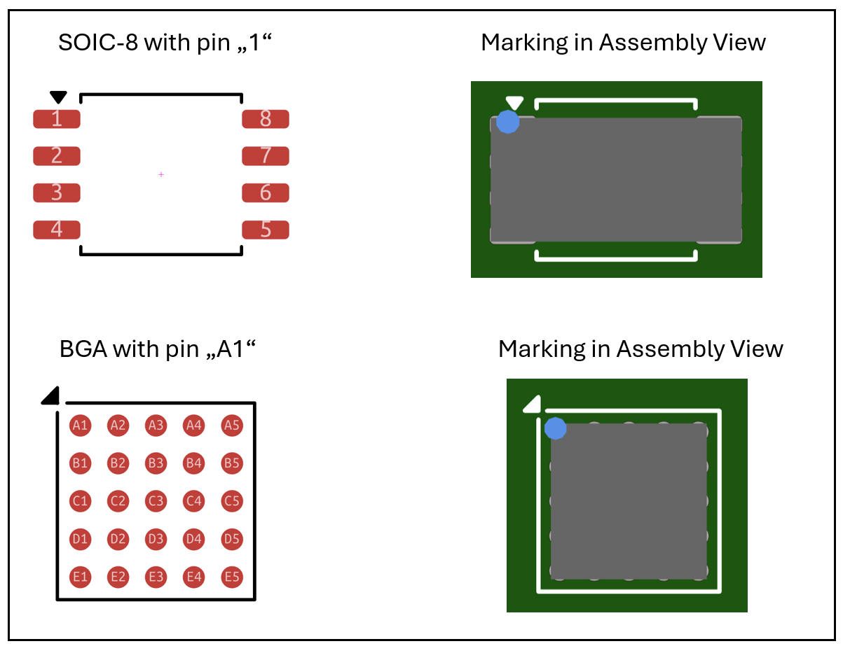
- For components with 3 or more pads: The polarity marker must point to Pad 1 or A1.
- For components with 2 pads: Orientation and polarity are based on the designator prefix (e.g., C, D, LED), pad names, and your EDA tool.
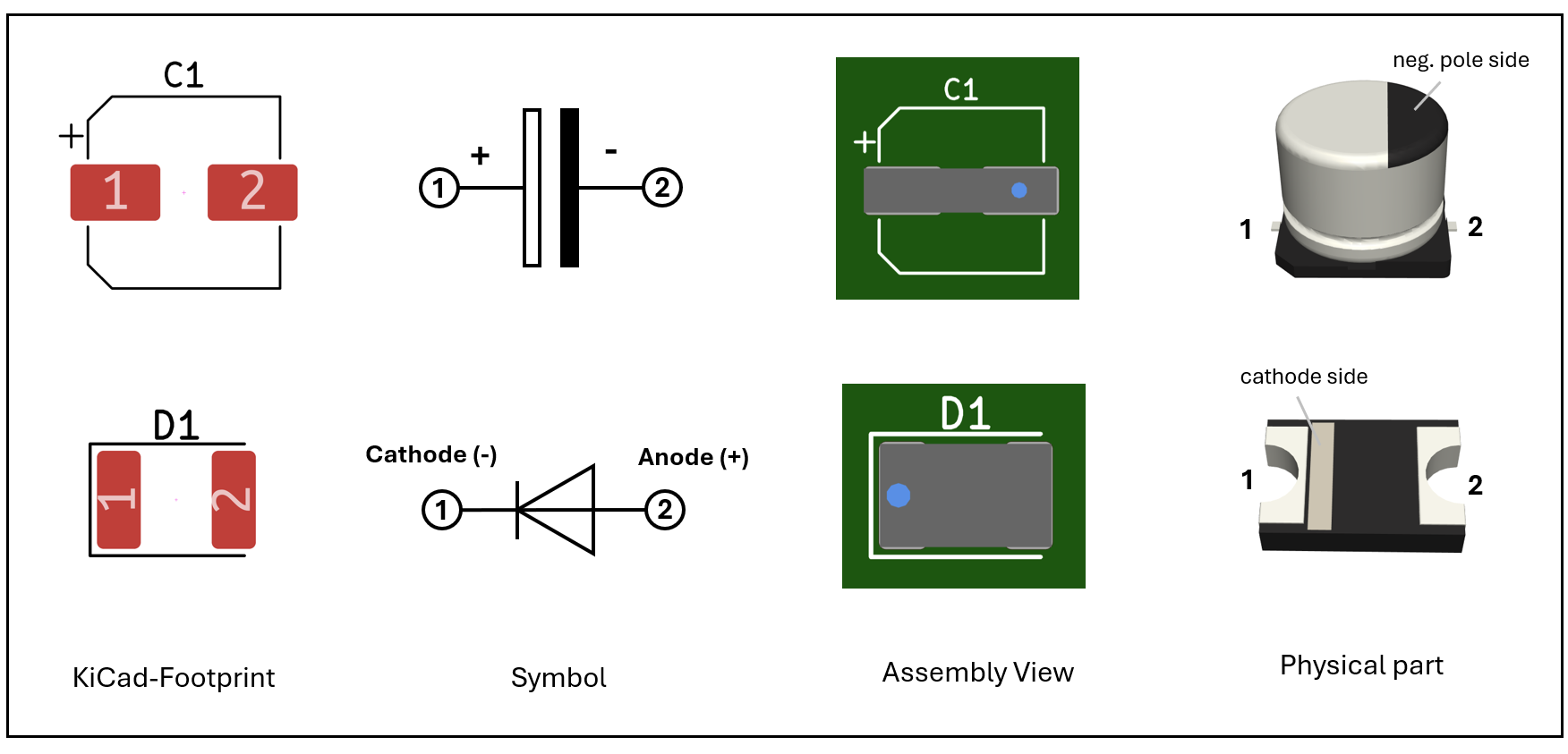
- For diodes, the marker points to the cathode.
- For capacitors (including tantalum), it points to the negative pole.
- See Table 1 below for more details.
- Components not covered by these rules are not auto-detected.
- Symmetric components without a marker will be placed without a specific orientation.
- If you’re using polarized components but no polarity marker is shown, please contact us.
Why This Matters
The correct orientation of polarized components is critical for your board to function. A reversed resistor may still work, but a reversed diode or IC will not.
Unfortunately, footprint libraries often do not strictly follow standards like IPC-7351B. Pad names and rotation values can be misleading, and silkscreen indicators are not reliable.
That’s why we’ve defined clear polarity rules — so that you can communicate the correct orientation of each component directly in your design data, and we can place them accordingly during assembly.
The Polarity Rules
This section describes the cases in which we determine a polarity and display it in the assembly view.
Note: If the polarity marker of a polarized component does not point to the correct pad (cathode / negative pole / Pin 1), please adapt the footprint accordingly — either by renaming pads or choosing a compatible footprint.
Orientation of components with 3 or more pads
Polarity is determined only by the position of pad “1” or “A1”.
The component’s reference designator is not evaluated.
Polarity (2 pad components)
We detect the component’s type (capacitor / diode) by evaluating the reference designator:
- Capacitors:
C#, e.g. C1, C2, C15, … - Diodes:
D#,LED#, e.g. D1, LED5, …
Based on the component’s type, the polarity (cathode / negative pole) is determind by the pad naming and the used EDA-tool.
We follow IPC-7351B, with an exception for Target3001!.
Table 1: Pad naming conventions for 2-pin capacitors and diodes
| Component Type | Capacitors (C#) |
Diodes (D#, LED#) |
|---|---|---|
| Negative pole (−) | Cathode (−) | |
| Default | 2, - | 1 , C, K |
| Target3001! | 2 | 2 |
Limitations and Final Check
- The system only recognizes the cases described above. Example: If you use a designator for a 2-pin diode like
"DIO2"instead of"D2", polarity won’t be detected. - If a component can only be placed in one orientation (e.g. SOT323), a marker is not needed.
- You must ensure that all polarized components have a polarity marker pointing to the correct pad (cathode / negative pole / Pin 1).
- By submitting your order, you confirm that all placements are correct.
See also our Rendering Guarantee for Amazing Assembly. - If your footprints don’t comply with our polarity rules, please get in touch — we may be able to set up a custom detection logic.