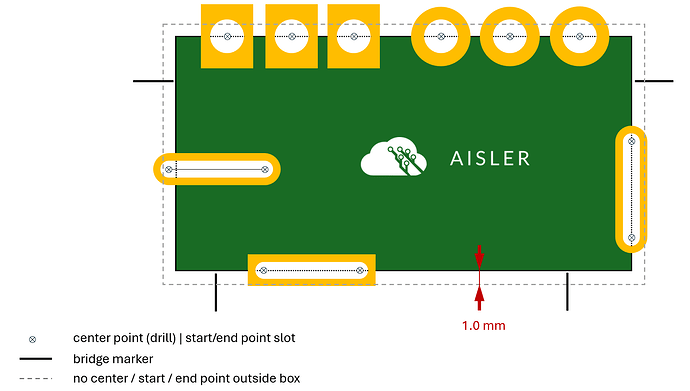
What are Castellated Holes?
Castellated Holes (a.k.a. Plated Half Holes, Castellations, … ) are a series of plated through holes or plated slots placed on the edges of the PCB and allow you to transform your PCB into a surface mounted sub-assembly. When cutting the board at the end of the manufacturing process, only a half of each plated hole remains in the PCB. These Plated Half Holes now serve as pads to solder the sub-assembly to the surface of the motherboard.
Which designs of Castellated Holes does AISLER support?
AISLER supports the half hole technique mentioned above - it is the easiest and most common way to design Castellated Holes. Please follow our design rules in the next section to get the best results.
How to design Castellated Holes?
Integrating Castellated Holes to your PCB is very easy. Just make sure to pay attention to the following points:
- Regular drills: Place the center point of every castellated hole exactly on the edge/ board outline of your PCB.
- Slots / elongated holes: Place start- and/or end point exactly on the edge / board outline of your PCB. Alternatively the slot (the connection line between start- and end point) must intersect the edge / board outline of your PCB.
- It is important that slots and drills are defined as plated-through in your EDA application. (In case you upload zipped Gerber files, please make sure to place the holes / slots in the *.drills_pth.xln file.)
- It is mandatory to use user defined bridges , otherwise we won’t recognize you castellated holes. Please see our article about bridges and frames.
- Each castellated hole must be located within a pad on each copper layer (on 4-layer boards also on the inner layers). This is necessary to achieve a sufficient stability of the copper sleeve.
- Please also make sure that the pad completely encloses the hole/slot. The requirements of the annular ring / pad size are the same as for conventional plated holes.
- Minimal drill diameter: 0.6 mm (0.024 in)
- Minimal slot diameter: 0.7 mm (0.028 in)
- Maximum slot diameter: 2.8 mm (0.11 in)
- Please make sure the slot is placed within the dashed box; otherwise we will delete it
How does it work?
If your PCB matches our design requirements (properly designed castellated holes + user defined bridges) we will manufacture the PCB in a thin frame. In the final mechanical processing, the castellated holes are treated separately to ensure a high quality of the edges.
As soon as your project fulfils both conditions, we will display a corresponding processing note in our preview.
What do you charge for the manufacturing of castellated holes?
The manufacturing of castellated holes is not charged additionally. However, the presence of castellated holes might affect the rating of your pcb (complex feature).
