We support the direct import of EAGLE board files, the necessary production files are created using a software pipeline in our backend, no need to worry about export parameters.
Note on EAGLE Versions
We support EAGLE files created with Version 7 and earlier. If you’re using EAGLE version 8 or 9, please update to Autodesk Fusion 360 and see Support for Autodesk Fusion360
Design Remarks
As we prepare your design files for manufacturing using an automated software pipeline, please contact our support before ordering, if you have any questions or want to make remarks, as we do not read notes included in your project files.
DRC Templates
We offer EAGLE Design Rule Files which include our layer stackups and all necessary design rules on Github.
How to import an EAGLE BRD file
Open up your PCB file and make sure all planes and polygons are updated, make sure to run the DRC to catch any errors, if there are any, please resolve them. Save your design.
You can upload the board file via drag and drop on the startpage or the Import Project in your project overview.
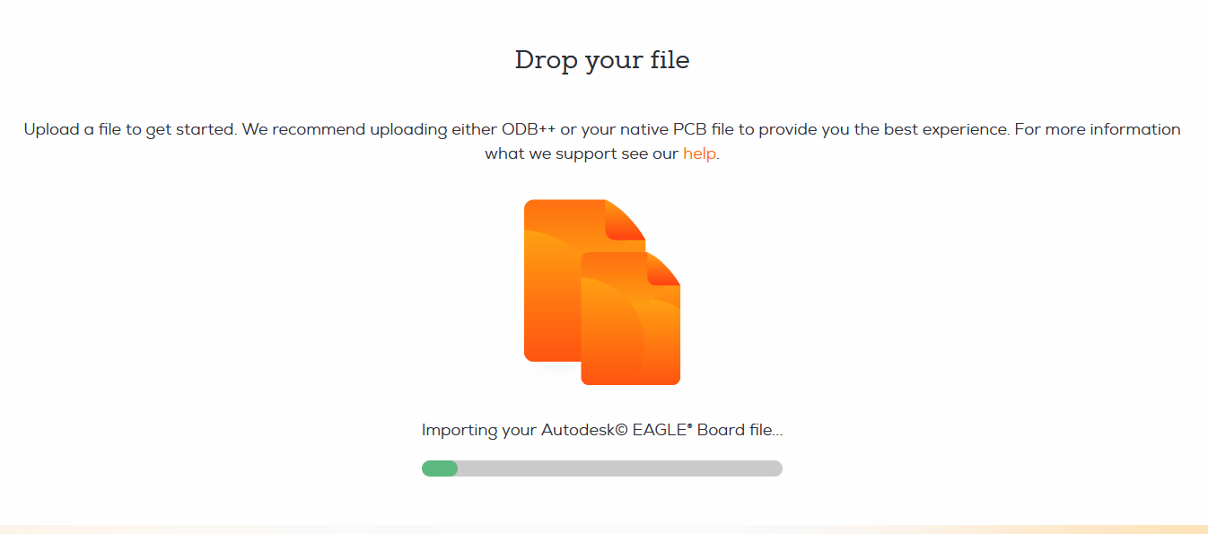
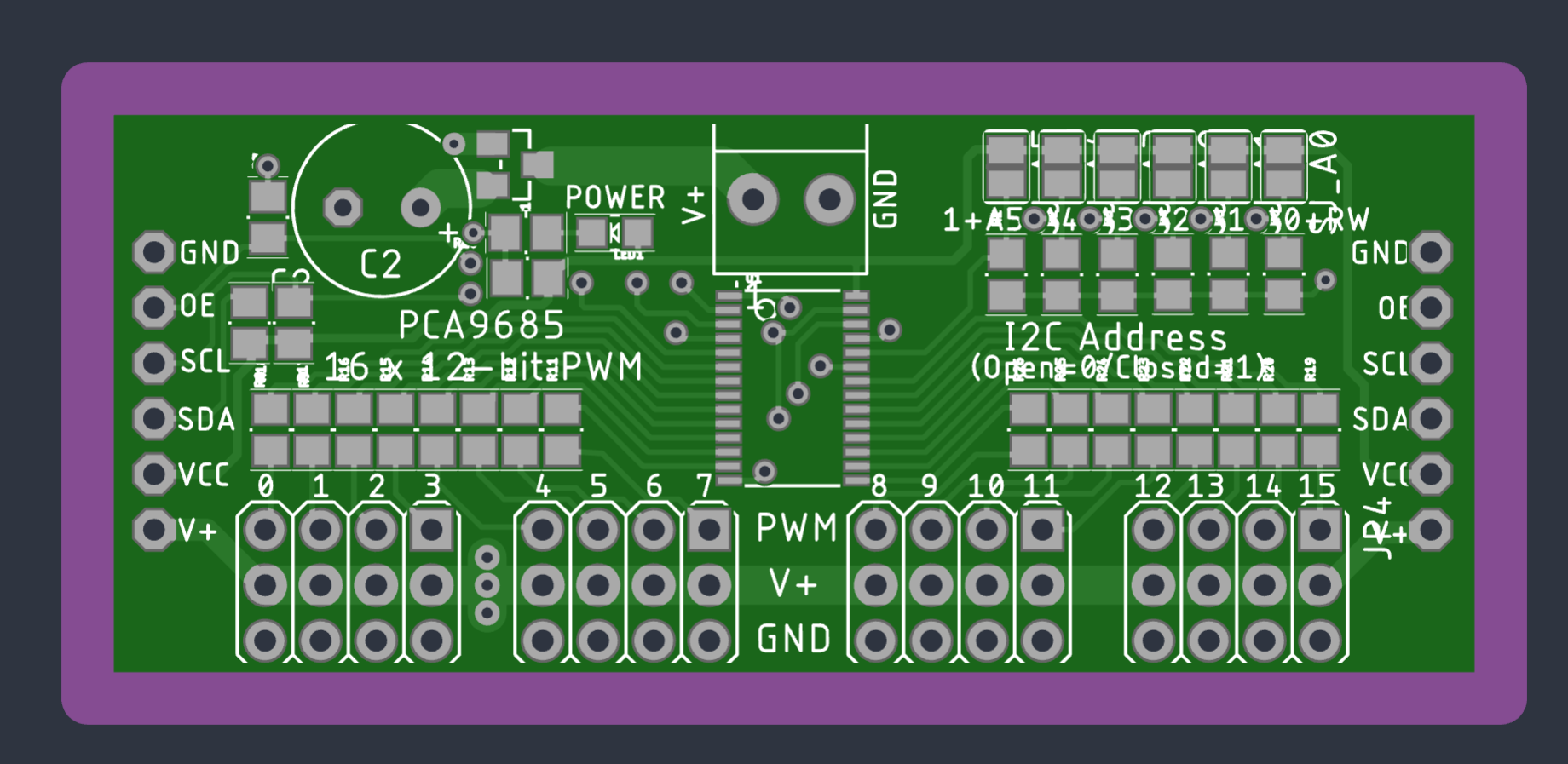
After we processed the board file you can inspect the boards using our board viewer.
We give a rendering guarantee that the boards are manufactured as displayed in our viewer. You can read this article if you are unsure how to use our board viewer or if you want to know how the rendering guarantee works.
Exporting a custom Gerber file from EAGLE
Please note: Use this only if you need. Our regular import (see above) is best for most use cases.
Follow this Guide in case you are using non-standard layers in your eagle project or want to exclude layers on export. Please note that assembly and electrical testing is not supported for Gerber uploads.
First things first, we prepare your Gerber files for manufacturing using an automated software pipeline, if you have any questions or want to make remarks, please contact our support prior to ordering, as we do not read notes included in your project files.
You need a CAM file, which you can download from our Github repository:
Select the 2 or 4 Layer CAM, depending on what you use in your project.
The CAM file is essentially an instruction set that tells EAGLE how your Layers are exported to the Gerber file.
Let’s look at an example of a custom Gerber Output:
When uploading a .brd file, we automatically import Layer 21,25 and 112 respectively tPlace, tNames and tSilk. In our example, this leads to a quite messy silkscreen. You could just go ahead and delete what you don’t want from the board/library, but this is quite tedious, so we would rather not do that. Instead, we will adjust what we export to our Gerber file.
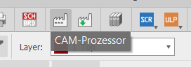
Open up your design and navigate to the CAM Processor .
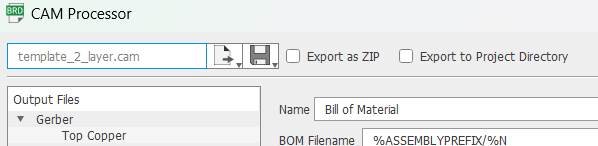
Use the dialog to navigate to the files you downloaded earlier and select the CAM file which corresponds to your stackup.
Now we can make adjustments to our Gerber Export. When Selecting Silkscreen Top we see that Layer 21 and 25 are exported to the corresponding Gerber file. On the right, you see a preview of the exported layers. Let’s remove layer 25/tNames using the Layer Selection.
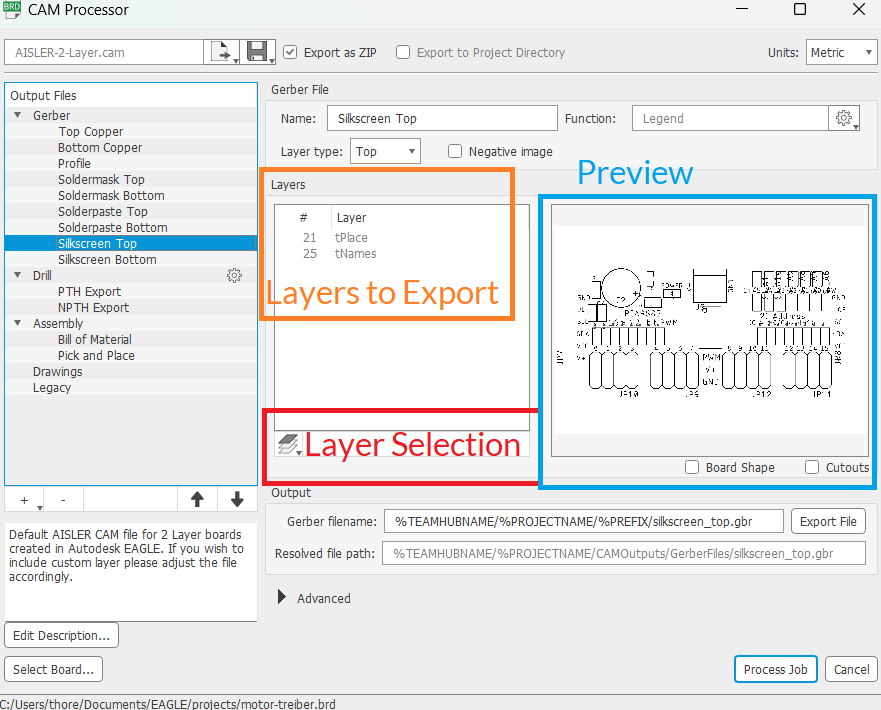
Preview of the silkscreen with layer tPlace and tName enabled.
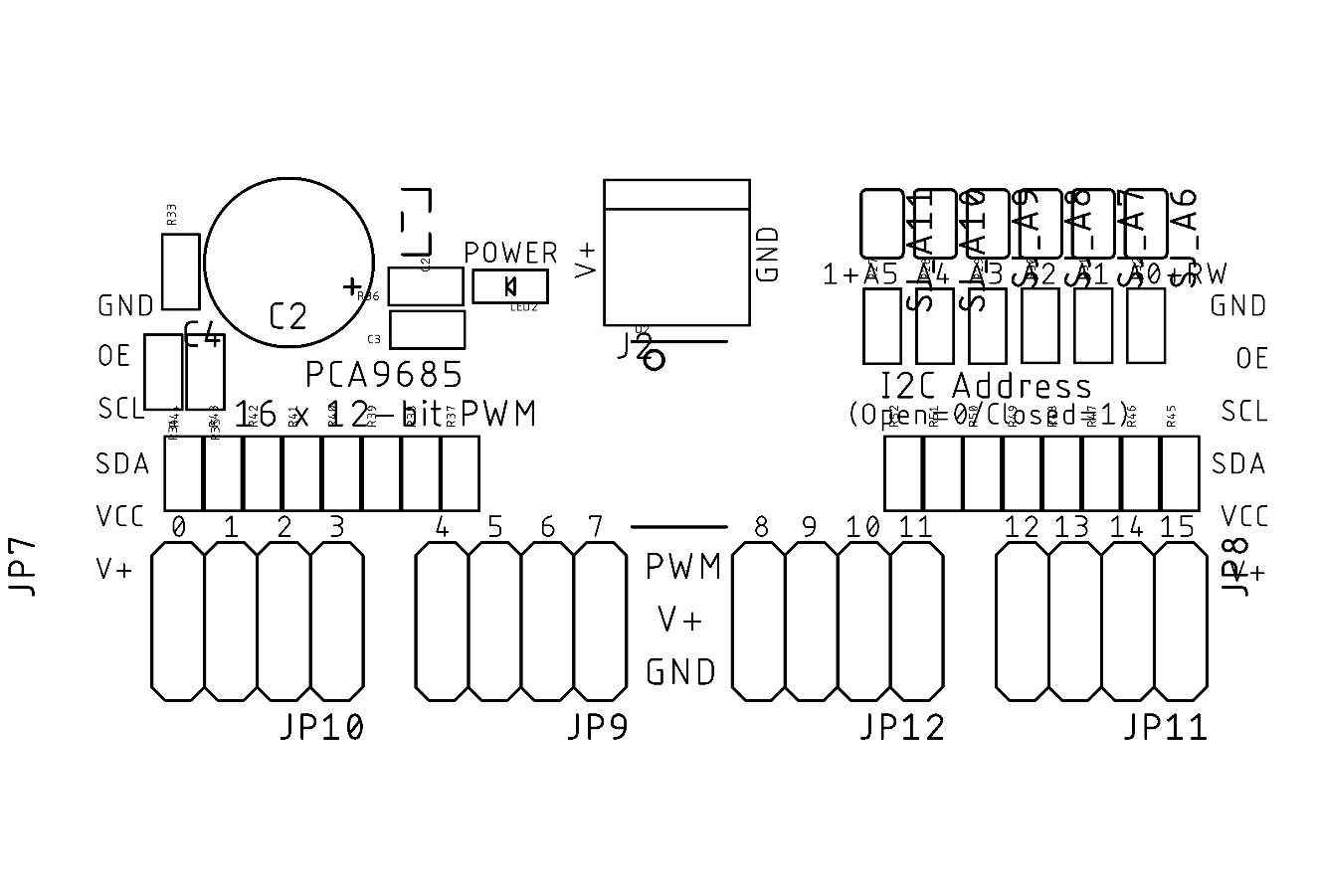
Preview of the silkscreen with just tPlace enabled.
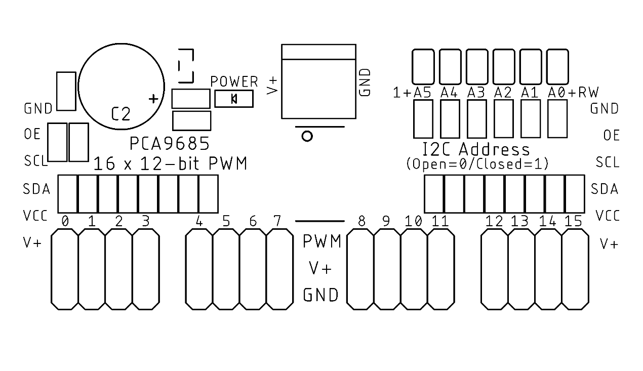
That looks much better  .
.
Let’s export the data by pressing the Process Job button and save the Gerber as .zip file.
That’s already everything you need.
Known PCB Design Tool issues
Issue: Custom layers are not imported when uploading a .brd file.
-
Description: Custom layers are not imported when uploading a .brd file from EAGLE, we only import the standard set of layers defined by Autodesk. Custom layers are ignored.
-
Workaround/Fix: If custom layers are used, a custom Gerber output can be created using the guide above.
Issue: Fillets in the board outline cannot be processed
-
Description: Unlike other Tools EAGLE exports Fillets as lines not arcs into the Gerber file, as a result, our software pipeline may be unable to automatically construct the board outline.
-
Workaround/Fix: We are actively working to adjust our software pipeline to account for this. If you encounter this issue, please contact our support team, we have a manual solution available, so we can fabricate your design.
Issue: Zero-width polygon zones
-
Description: Due to a bug in the CAM processor, polygons filled with a stroke width of zero cause a never ending export process. We detect these cases and stop and further processing.
-
Workaround/Fix: For XML based files we automatically set the stroke width to 0.2mm, however, for everything else this has do be done manually. Check all filled polygons for a stroke width of zero and set this to at least 0.1mm.